OPTIREG™ SBC TLE9274QXV33
Serial Peripheral Interface
Field
CAN
Bits
Type
Description
1:0
rwh
HS-CAN module mode
00B , CAN OFF
01B , CAN is wake capable
10B , CAN Receive-Only mode
11B , CAN Normal mode
Note: In case CAN transceiver is configured to ‘11’ while going to SBC Stop or Sleep mode, it will be
automatically set to wake capable (‘01’). However, the SPI bits will stay unchanged, i.e. once the SBC
returns to Normal mode, the previous state is recovered again (‘11’). The Receive-Only mode (‘10’) has to
be selected by purpose before entering SBC Stop mode. For more details, refer to Figure 18.
In case of entering SBC Sleep mode, the CAN transceiver has to be set to CAN wake capable or CAN OFF
mode before.
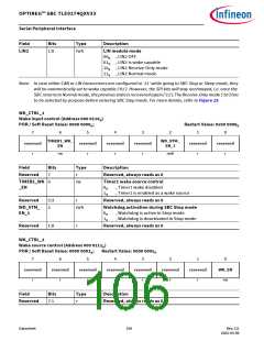
In case LIN transceiver is configured to ‘11’ while going to SBC Stop or Sleep mode, it will be automatically
set to wake capable (‘01’). However, the SPI bits will stay unchanged, i.e. once the SBC returns to Normal
mode, the previous state is recovered again (‘11’).The Receive-Only mode (‘10’) has to be selected by
purpose before entering SBC Stop mode. For more details, refer to Figure 25.
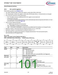
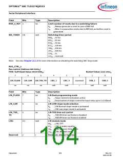
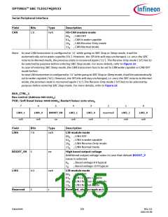
BUS_CTRL_2
Bus control (Address 000 0101B)
POR / Soft Reset Value: 0000 0000B; Restart Value: xx0x x0xxB
7
6
5
4
3
2
1
0
LIN4_1
LIN4_0
BOOST_VH
LIN3_1
LIN3_0
reserved
LIN2_1
LIN2_0
r
rwh
rwh
rw
rwh
rwh
r
rwh
rwh
Field
Bits
Type
Description
LIN4
7:6
rwh
LIN module mode
00B , LIN4 OFF
01B , LIN4 is wake capable
10B , LIN4 Receive-Only mode
11B , LIN4 Normal mode
BOOST_VH
LIN3
5
rw
rwh
r
High boost output voltage
Additional output voltage value in case that default BOOST_V
value is selected.
0B
1B
, Boost voltage 8 V typical
, Boost voltage 10 V typical
4:3
2
LIN module mode
00B , LIN3 OFF
01B , LIN3 is wake capable
10B , LIN3 Receive-Only mode
11B , LIN3 Normal mode
Reserved
Reserved, always reads as 0
Datasheet
105
Rev.2.0
2022-05-06

 INFINEON [ Infineon ]