OPTIREG™ SBC TLE9274QXV33
Serial Peripheral Interface
Field
Bits
Type
Description
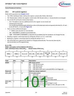
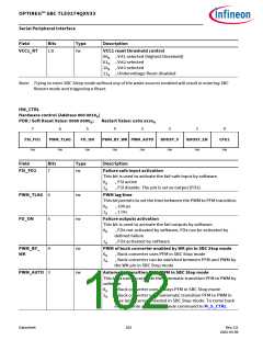
VCC1_RT
1:0
rw
VCC1 reset threshold control
00B , Vrt1 selected (highest threshold)
01B , Vrt2 selected
10B , Vrt3 selected
11B , Undervoltage Reset disabled
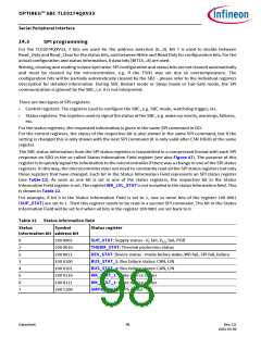
Note: Trying to enter SBC Sleep mode without any of the wake sources enabled will result in entering SBC
Restart mode and triggering a Reset.
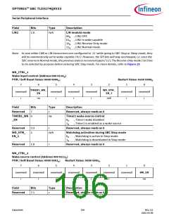
HW_CTRL
Hardware control (Address 000 0010B)
POR / Soft Reset Value: 0000 0000B;
Restart Value: xx0x xxxxB
7
6
5
4
3
2
1
0
FSI_FO2
PWM_TLAG
FO_ON
PWM_BY_WK PWM_AUTO
BOOST_V
BOOST_EN
CFG2
R
rw
rw
rw
rw
rw
rw
rw
rw
Field
Bits
Type
Description
FSI_FO2
PWM_TLAG
FO_ON
7
rw
rw
rw
Failure safe input activation
This bit is used to activate the fail-safe input by software.
0B
1B
, FSI active
, FSI disable. The pin is set as output (FO2)
6
5
PWM lag time
This bit permits to set the time between the PWM to PFM transition.
0B
1B
, 100 µs
, 1 ms
Failure outputs activation
This bit is used to activate the fail outputs by software.
0B
, FOx not activated by software, FOx can be activated by
defined failure
1B
, FOx activated by software
PWM_BY_
WK
4
3
rw
rw
PWM of buck converter enabled by WK pin in SBC Stop mode
0B
1B
, Buck converter uses PFM in SBC Stop mode
, Buck converter can be switched between PFM and PWM by
the WK pin in SBC Stop mode
PWM_AUTO
Automatic transition PFM-PWM in SBC Stop mode
This bit is used to activate the automatic transition PFM to PWM by
software.
0B
1B
, Buck converter uses always PFM in SBC Stop mode
, Buck converter uses automatic transition PFM to PWM in
case large current needed in SBC Stop mode. To come back
in PFM, write a SBC Stop mode command to M_S_CTRL
Datasheet
102
Rev.2.0
2022-05-06

 INFINEON [ Infineon ]