TLD7002-16ES
Datasheet
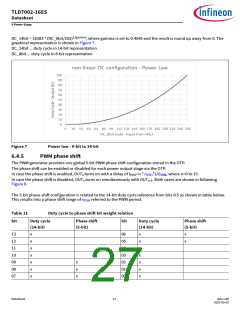
6 Power Stage
I
= I
− V
− VDER_START × k
OUTDER
OUT
GPIN0
DER
(3)
k
= I
− 5 . 625 mA / VDER_STOP/VDER_START
DER
OUT
VDER_start and VDER_stop are configured globally and stored in the OTP.
The GPIN0 derating function can be enabled or disabled via the OTP configuration.
In case the GPIN0 derating feature is enable, the power shif feature is not available.
IOUT
VDER_STOP
VGPIN
VDER_START
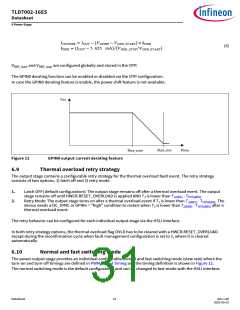
Figure 11
GPIN0 output current derating feature
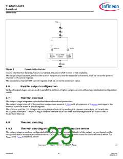
6.9
Thermal overload retry strategy
The output stage contains a configurable retry strategy for the thermal overload fault event. The retry strategy
consists of two options, 1) latch off and 2) retry mode.
1.
2.
Latch OFF( default configuration): The output stage remains off afer a thermal overload event. The output
stage remains off until HWCR.RESET_OVERLOAD is applied AND TJ is lower than TJ(ABS) - THYS(ABS)
Retry Mode: The output stage turns on afer a thermal overload event if TJ is lower than TJ(ABS) - THYS(ABS). The
device needs a DC_SYNC or GPINn = "high" condition to restart when TJ is lower than TJ(ABS) - THYS(ABS) afer a
thermal overload event.
.
The retry behavior can be configured for each individual output stage via the HSLI interface.
In both retry strategy options, the thermal overload flag OVLD has to be cleared with a HWCR.RESET_OVERLOAD
except during the reconfirmation cycle when fault management configuration is set to 1, where it is cleared
automatically
6.10
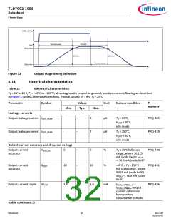
Normal and fast switching mode
The power output stage provides an individual configurable normal and fast switching mode (slew rate) where the
turn-on and turn-off timings are defined in PWM output timing and the timing definition is shown in Figure 12.
The normal switching mode is the default configuration and can be changed to fast-mode with the HSLI interface.
Datasheet
31
Rev.1.00
2022-05-03

 INFINEON [ Infineon ]