TLD7002-16ES
Datasheet
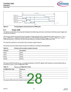
6 Power Stage
VLED
OUTn
OUTn+1
Power Shift
Control
GND
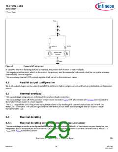
Figure 9
Power shif principle
In case the thermal derating feature is enabled, the power shif feature is not available.
The target output current, which is the sum of the primary and the secondary channels, shall be set in the primary
channel OTP current register.
The secondary channel OTP current register shall be set to the minimum value.
6.6
Parallel output configuration
Up to all output stages can be used in parallel to achieve a higher output current without any dedicated configuration
needs.
6.7
Thermal overload
The output stage integrates an individual thermal overload protection.
The output stage turns off if the junction temperature exceeds TJ(ABS) with a hysteresis of THYS(ABS) and reports the
thermal overload event in a fault register.
The LCU can poll the OVLD flag in the output status byte or by reading the channel status byte OUTn with the
READ_OST command. The OVLD flag is cleared afer the fault has been acknowledged with an explicit HWCR
frame from the LCU.
6.8
Thermal derating
6.8.1
Thermal derating with integrated temperature sensor
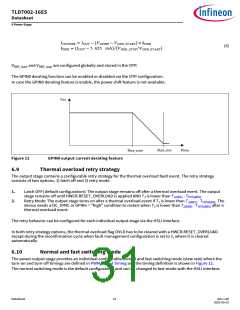
The output stage provides a configurable thermal derating (thermal foldback) of the output current based on the
integrated device temperature measurement. Each output stage starts to decrease the current linearly when TJ ≥
TJstart until TJstop is reached, where
IOUTDER
=
IOUT − TJ − TJstart × kDER
(1)
Datasheet
29
Rev.1.00
2022-05-03

 INFINEON [ Infineon ]