TLD7002-16ES
Datasheet
6 Power Stage
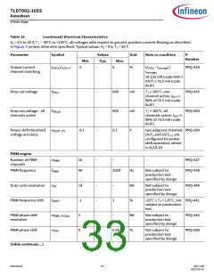
Table 15
(continued) Electrical Characteristics
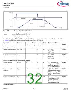
VS = 6 V to 20 V, TJ = -40°C to +150°C, all voltages with respect to ground, positive currents flowing as described
in Figure 2 (unless otherwise specified). Typical values: VS = 9 V, TJ = 25°C
Parameter
Symbol
Values
Typ.
Unit
Note or condition
P-
Number
Min.
Max.
Output current
channel matching
IOUTn, OUTn+1
I
-5
–
5
ꢀ
(IOUTn - Iaverage) /
Iaverage,
PRQ-434
10.125 mA (code 0x4) ≤
IOUT ≤ 76.5 mA (code
0x3F)
Drop out voltage
VDR,1
–
–
–
600
850
0.1
mV
mV
V
TJ ≤ 105°C, one
PRQ-435
PRQ-604
channel active, IOUT
≥
90ꢀ of 76.5 mA (code
0x3F)
Drop out voltage - all
channels active
VDR,all
TJ < 105°C, all
channels active, IOUT
90ꢀ of 76.5 mA (code
0x3F)
≥
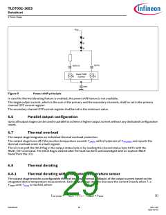
Power shif threshold aVOUT_PS
voltage accuracy
-0.1
two adjacent channels PRQ-689
OUTn and OUTn+1 are
configured for power
shif operation, where
n=0,2,8,10
PWM engine
Number of PWM
channels
nPWM
fPWM
16
99
–
–
–
–
–
PRQ-437
PRQ-438
PWM frequency
2020
Hz
Not subject to
production test -
specified by design
Duty cycle resolution
PWM frequency drif
nDC
14
-1
5
–
–
–
-
–
Bit
ꢀ
Not subject to
production test -
specified by design
PRQ-440
fDRIFT
1
-20°C ≤ TJ < 125°C, not PRQ-441
subject to production
test
PWM phase shif
resolution
nPWM_PH,Res
–
Bit
ꢀ
Not subject to
production test -
specified by design
PRQ-442
PWM phase shif
nPSH
0
6.05
Not subject to
PRQ-688
production test -
specified by design
(table continues...)
Datasheet
33
Rev.1.00
2022-05-03

 INFINEON [ Infineon ]