TLD7002-16ES
Datasheet
6 Power Stage
6.4
PWM Generator
PWM function
6.4.1
The device operates each power output stage with a PWM function containing
•
•
•
one configurable duty cycle per channel
one global PWM frequency and
one global PWM phase shif
The device sinks current on HSLI request or GPIN request on each output channel in ≤tON time.
This delay depends on the PWM frequency and on the phase shif according to the following approximate formula:
tON=1/fPWM+n*tPHS
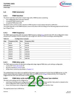
6.4.2
PWM frequency
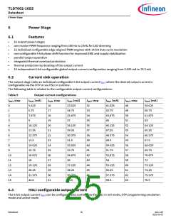
The PWM engine operates with one master PWM frequency setting fPWM stored in the OTP. The configuration steps
should cover multiples of 50 Hz and 60 Hz in the range from 100 Hz to 2 kHz according to following table:
Table 10
Configuration example
Step
Frequency [Hz]
Step
8
Frequency [Hz]
0
1
2
3
4
5
6
7
99.90
662.08
723.38
781.25
899.50
1199.00
1502.40
1799.00
1997.00
200.32
239.65
300.48
359.78
399.89
539.03
600.96
9
10
11
12
13
14
15
6.4.3
PWM duty cycle
The PWM engine provides 16 individual configurable edge-aligned PWM duty cycle settings configurable
•
•
•
via the OTP in fail-safe mode OR
the HSLI interface in active mode
GPINn direct control as described in Chapter 5.3
The updated duty cycle values are applied to the power stages synchronous to the internal PWM period. e.g. the
power output duty cycle change is seen latest afer one PWM period (1/fPWM) independently if the change was
triggered by the HSLI, fail-safe mode or GPINn control.
6.4.4
PWM duty cycle configuration - linear or power-law relation
The duty cycle setting can be configured as
•
•
non-linear 8-bit duty cycle configuration by using the DC_UPDATE frame and DLC=0x4, which is related to the
8-bit configuration with a power law relation to the 14-bit resolution OR
linear 14-bit duty cycle configuration by using the DC_UPDATE frame and DLC=0x6.
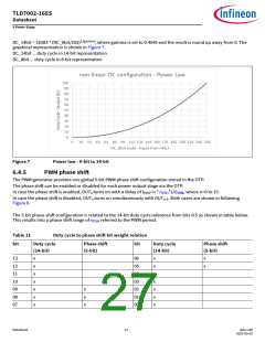
The applied power law is defined as:
Datasheet
26
Rev.1.00
2022-05-03

 INFINEON [ Infineon ]