TDA5235
Appendix
Register Description
Field
Bits
Type
Description
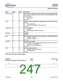
INITPLLHOLD 6
w
Init PLL after coming from HOLD (when new channel programmed).
This requires an additional Channel Hop Time before initialization of the
Digital Receiver.
0B
1B
No init of PLL
Init of PLL
Reset: 0H
HOLD
5
4
w
w
Holds the chip in the Register Configuration state (only in Run Mode
Slave)
0B
1B
Normal Operation
Jump into the Register Config state Hold
Reset: 0H
CLKOUTEN
CLK_OUT Enable
0B
1B
Disabled
Enable programmable clock output
Reset: 1H
UNUSED
MCS
3
2
w
w
UNUSED
Reset: 0H
Multi Configuration Selection (Run Mode Slave / Self Polling Mode)
0B
1B
Config A / Config A
Config B / Config A + B
Reset: 0H
SLRXEN
MSEL
1
0
w
w
Slave Receiver Enable
This Bit is only used in Operating Mode Run Mode Slave / Sleep Mode
0B
1B
Receiver is in Sleep Mode
Receiver is in Run Mode Slave
Reset: 0H
Operating Mode Selection
0B
1B
Run Mode Slave / Sleep Mode
Self Polling Mode
Reset: 0H
Wakeup Peak Detector Readout Register
RSSIPWU
Offset
0A7H
Reset Value
00H
Wakeup Peak Detector Readout Register
ꢀ
ꢁ
566,3:8
ꢂ
Data Sheet
247
V1.0, 2010-02-19

 INFINEON [ Infineon ]