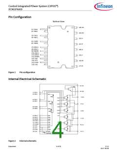
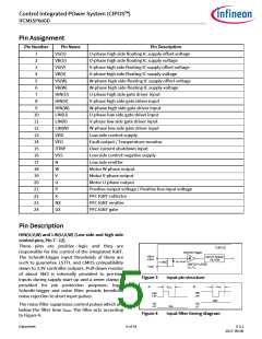
Control Integrated POwer System (CIPOS™)
IFCM15P60GD
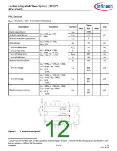
PFC Section
(VGE = 15V and TJ = 25°C, if not stated otherwise)
Value
Description
Condition
IC = 250µA
Symbol
Unit
min
650
650
-20
-
max
-
Max. blocking voltage
Repetitive peak reverse voltage
Gate-emitter voltage
VCES
VRRM
VGE
Ii
V
V
V
A
IR = 250µA
-
20
30
Input RMS current
TJ ≤ 150°C , TC = 25°C
TJ ≤ 150°C , TC = 25°C
less than 1ms, non-
repetitive
Maximum peak input current
Power dissipation
Ii(peak)
-
60
A
Ptot
TJ
-
85.6
150
W
Operating junction temperature
range
-40
°C
Single IGBT thermal resistance,
junction-case
RthJC
-
-
1.46
2.76
K/W
K/W
Single diode thermal resistance,
junction-case
RthJCD
Recommended Operation Conditions
All voltages are absolute voltages referenced to VSS -potential unless otherwise specified.
Value
Description
DC link supply voltage of P-N
Symbol
Unit
min
0
typ
-
max
450
VPN
VBS
VDD
V
V
V
High side floating supply voltage (VB vs. VS)
Low side supply voltage
13.5
14.5
-
18.5
18.5
16
ΔVBS,
ΔVDD
-1
-1
1
1
Control supply variation
-
-
V/µs
V
VIN
VITRIP
0
0
5
5
Logic input voltages LIN,HIN,ITRIP
Between VSS - N and NX(including surge)
PFC IGBT gate-emitter voltage
VSS
VGE
RG
-5
14
-
-
5
18
-
V
V
-
10
4.7
10
Ω
PFC IGBT external gate parameters
CGE
RGE
-
-
nF
kΩ
-
-
Datasheet
8 of 18
V 2.2
2017-09-06

 INFINEON [ Infineon ]