Control Integrated POwer System (CIPOS™)
IFCM15P60GD
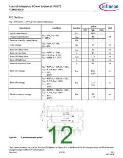
PFC Section
(VGE = 15V and TJ = 25°C, if not stated otherwise)
Value
typ
1800
45
Description
Input capacitance
Condition
Symbol
Unit
min
max
Cies
Coes
Cres
-
-
-
-
-
-
VCE = 25V, VGE = 0V,
f = 1MHz
Output capacitance
pF
nC
Reverse transfer capacitance
7
VDC = 520V, IC = 30A,
VGE = 15V
Gate charge
QG
-
70
-
Turn-on delay time
Turn-on rise time
Turn-off delay time
Turn-off fall time
td(on)
tr
td(off)
tf
-
-
-
-
-
20
45
-
-
-
-
-
ns
ns
ns
ns
ns
VDC = 400V, IC = 30A,
RG = 10Ω, CGE = 4.7nF,
RGE = 10kΩ, TJ = 25°C
115
30
Reverse recovery time
trr
80
VDC = 400V, IC = 30A, RG = 10Ω,
CGE = 4.7nF, RGE = 10kΩ
TJ = 25°C
150°C
Turn-on energy
Eon
Eoff
Erec
-
-
835
1025
-
-
µJ
µJ
µJ
VDC = 400V, IC = 30A, RG = 10Ω,
CGE = 4.7nF, RGE = 10kΩ
TJ = 25°C
150°C
Turn-off energy
-
-
315
395
-
-
VDC = 400V, IC = 30A, RG = 10Ω,
CGE = 4.7nF, RGE = 10kΩ
TJ = 25°C
150°C
Diode recovery energy
-
-
95
170
-
-
Figure 6
TC measurement point1
1 Any measurement except for the specified point in figure 6 is not relevant for the temperature verification and
brings wrong or different information.
Datasheet
12 of 18
V 2.2
2017-09-06

 INFINEON [ Infineon ]