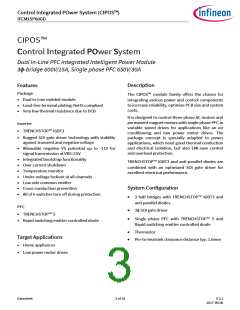
Control Integrated POwer System (CIPOS™)
IFCM15P60GD
Absolute Maximum Ratings
(VDD = 15V and TJ = 25°C, if not stated otherwise)
Module Section
Value
Description
Condition
Symbol
Unit
min
-40
max
125
-
Storage temperature range
Isolation test voltage
Tstg
VISOL
TC
°C
V
RMS, f = 60Hz, t =1min
Refer to Figure 6
2000
-40
Operating case temperature range
125
°C
Inverter Section
Value
Description
Condition
Symbol
Unit
min
max
-
Max. blocking voltage
IC = 250µA
VCES
VPN
600
V
V
DC link supply voltage of P-N
DC link supply voltage (surge) of P-N
Output current
Applied between P-N
Applied between P-N
TC = 25°C , TJ < 150°C
less than 1ms
-
-
450
500
15
VPN(surge)
IC
IC(peak)
tSC
V
-15
-30
-
A
Maximum peak output current
Short circuit withstand time1
Power dissipation per IGBT
30
A
VDC ≤ 400V, TJ = 150°C
5
µs
W
Ptot
-
49.8
Operating junction temperature
range
TJ
-40
150
2.51
4.67
°C
Single IGBT thermal resistance,
junction-case
RthJC
RthJCD
-
-
K/W
K/W
Single diode thermal resistance,
junction-case
Control Section
Value
Description
Condition
Symbol
Unit
min
-1
max
20
Module supply voltage
VDD
VBS
V
V
High side floating supply voltage (VB vs. VS)
-1
20
VIN
VITRIP
-1
-1
10
10
Input voltage
LIN, HIN, ITRIP
V
Inverter switching frequency
PFC switching frequency
fPWM
-
-
20
60
kHz
kHz
fPWM(PFC)
1 Allowed number of short circuits: <1000; time between short circuits: > 1s.
Datasheet
7 of 18
V 2.2
2017-09-06

 INFINEON [ Infineon ]