Quasi-Resonant, 800V CoolSET™ in DS0-12 Package
Functional Description
Table 2
VFB
up/down counter action
Always lower than VFBZL
Count upwards till 7
Once higher than VFBZL, but always lower than VFBZH
Once higher than VFBZH, but always lower than VFBR1
Once higher than VFBR1
Stop counting, no value changing
Count downwards till 1
Set up/down counter to 1
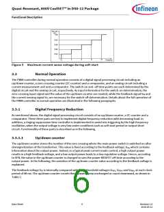
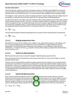
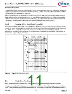
In the ICE2QR1080G, the number of zero crossing is limited to 7. Therefore, the counter varies between 1 and 7,
and any attempt beyond this range is ignored. When VFB exceeds VFBR1 voltage, the up/down counter is reset to
1, in order to allow the system to react rapidly to a sudden load increase. The up/down counter value is also
reset to 1 at the start-up time, to ensure an efficient maximum load start up. Figure 6 shows some examples on
how up/down counter is changed according to the feedback voltage over time.
The use of two different thresholds VFBZL and VFBZH to count upward or downward is to prevent frequency
jittering when the feedback voltage is close to the threshold point. However, for a stable operation, these two
thresholds must not be affected by the foldback current limitation (see 3.4.1), which limits the VCS voltage.
Hence, to prevent such situation, the threshold voltages, VFBZL and VFBZH, are changed internally depending on
the line voltage levels.
clock
T=48ms
t
t
VFB
VFBR1
VFBZH
VFBZL
Up/down
counter
1
3 1
1 1
4 1
Case 1
4
2
7
5
3
7
6
4
7
6
4
7
6
6
4
7
5
4
2
5
Case 2
Case 3
4
7
3
6
Figure 6 Up/down counter operation
3.3.1.2
Zero crossing (ZC counter)
In the system, the voltage from the auxiliary winding is applied to the zero-crossing pin through a RC network,
which provides a time delay to the voltage from the auxiliary winding. Internally this pin is connected to a
clamping network, a zero-crossing detector, an output overvoltage detector and a ringing suppression time
controller.
During on-state of the power switch a negative voltage applies to the ZC pin. Through the internal clamping
network, the voltage at the pin is clamped to certain level.
Data Sheet
7
Revision 1.0
2016-05-12

 INFINEON [ Infineon ]