Quasi-Resonant, 800V CoolSET™ in DS0-12 Package
Functional Description
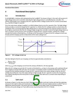
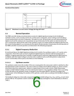
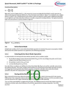
Vcs_sst
(V)
1.00
0.83
0.66
0.49
0.32
ton
3
6
9
12
Time(ms)
Figure 5 Maximum current sense voltage during soft start
3.3
Normal Operation
The PWM controller during normal operation consists of a digital signal processing circuit including an
up/down counter, a zero-crossing counter (ZC counter) and a comparator, and an analog circuit including a
current measurement unit and a comparator. The switch-on and -off time points are each determined by the
digital circuit and the analog circuit, respectively. As input information for the switch-on determination, the
zero-crossing input signal and the value of the up/down counter are needed, while the feedback signal VFB and
the current sensing signal VCS are necessary for the switch-off determination. Details about the full operation of
the PWM controller in normal operation are illustrated in the following paragraphs.
3.3.1
Digital Frequency Reduction
As mentioned above, the digital signal processing circuit consists of an up/down counter, a ZC counter and a
comparator. These three parts are key to implement digital frequency reduction with decreasing load. In
addition, a ringing suppression time controller is implemented to avoid mis-triggering by the high frequency
oscillation, when the output voltage is very low under conditions such as soft start period or output short
circuit. Functionality of these parts is described as in the following.
3.3.1.1
Up/down counter
The up/down counter stores the number of the zero crossing where the main power switch is switched on after
demagnetization of the transformer. This value is fixed according to the feedback voltage, VFB, which contains
information about the output power. Indeed, in a typical peak current mode control, a high output power
results in a high feedback voltage, and a low output power leads to a low regulation voltage. Hence, according
to VFB, the value in the up/down counter is changed to vary the power MOSFET off-time according to the
output power. In the following, the variation of the up/down counter value according to the feedback voltage is
explained.
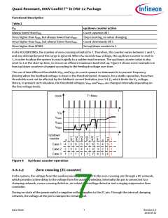
The feedback voltage VFB is internally compared with three threshold voltages VFBZL, VFBZH and VFBR1, at each clock
period of 48 ms. The up/down counter counts then upward, keep unchanged or count downward, as shown in
Table 2.
Data Sheet
6
Revision 1.0
2016-05-12

 INFINEON [ Infineon ]