Quasi-Resonant, 800V CoolSET™ in DS0-12 Package
Functional Description
3
Functional Description
3.1
Introduction
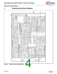
In ICE2QR1080G, a startup cell is integrated into the CoolMOS™. As shown in Figure 3, the start cell consists of a
high voltage device and a controller, whereby the high voltage device is controlled by the controller. The
startup cell provides a pre-charging of the VCC capacitor till VCC voltage reaches the VCC turned-on threshold
VVCCon and the IC begins to operate.
Once the mains input voltage is applied, a rectified voltage shows across the capacitor Cbus. The high voltage
device provides a current to charge the VCC capacitor CVCC. Before the VCC voltage reaches a certain value, the
amplitude of the current through the high voltage device is only determined by its channel resistance and can
be as high as several mA. After the VCC voltage is high enough, the controller controls the high voltage device so
that a constant current around 1 mA is provided to charge the VCC capacitor further, until the VCC voltage
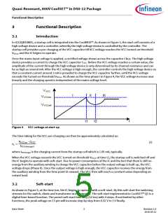
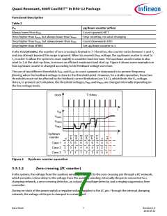
exceeds the turned-on threshold VVCCon. As shown as the time phase I in Figure 4, the VCC voltage increase near
linearly and the charging speed is independent of the mains voltage level.
VVCC
I
II
III
VVCCon
VVCCoff
t2
t
t1
Figure 4
VCC voltage at start up
The time taking for the VCC pre-charging can then be approximately calculated as:
푉ꢀ퐶퐶표푛 ∙ ꢁꢀ퐶퐶
푡1 =
(1)
퐼ꢀ퐶퐶푐ℎ푎푟ꢂ푒2
where IVCCcharge2 is the charging current from the startup cell which is 1.05 mA, typically.
When the VCC voltage exceeds the VCC turned-on threshold VVCCon at time t1, the startup cell is switched off and
the IC begins to operate with soft-start. Due to power consumption of the IC and the fact that there is still no
energy from the auxiliary winding to charge the VCC capacitor before the output voltage is built up, the VCC
voltage drops (Phase II). Once the output voltage is high enough, the VCC capacitor receives the energy from
the auxiliary winding from the time point t2 onward. The VCC then will reach a constant value depending on
output load.
3.2
Soft-start
As shown in Figure 5, at the time ton, the IC begins to operate with a soft-start. By this soft-start the switching
stresses for the switch, diode and transformer are minimized. The soft-start implemented in CoolSET™ Q1 is a
digital time-based function. The preset soft-start time is tSS (12 ms) with 4 steps. If not limited by other
functions, the peak voltage on CS pin will increase step by step from 0.32 V to 1 V finally.
Data Sheet
5
Revision 1.0
2016-05-12

 INFINEON [ Infineon ]