Quasi-Resonant, 800V CoolSET™ in DS0-12 Package
Functional Description
푉퐵푈푆 ∙ 푁푎
(5)
퐼푍퐶
=
푅푍퐶1 ∙ 푁푝
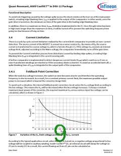
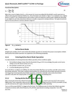
When this current is higher than IZC_FS, the amount of current exceeding this threshold is used to generate an
offset to decrease the maximum limit on VCS. Since the ideal curve shown in Figure 7 is a nonlinear one, a digital
block in CoolSETTM Q1 is implemented to get a better control of maximum output power. Additional advantage
to use digital circuit is the production tolerance is smaller compared to analog solutions. The typical maximum
limit on VCS versus the ZC current is shown in Figure 8.
Figure 8
VCS_max versus IZC
3.5
Active Burst Mode
At light load condition, the IC enters Active Burst Mode operation to minimize the power consumption. Details
about Active Burst Mode operation are explained in the following paragraphs.
3.5.1
Entering Active Burst Mode Operation
For determination of entering Active Burst Mode operation, three conditions apply:
the feedback voltage is lower than the threshold of VFBEB (1.25 V). Accordingly, the peak current sense
voltage across the shunt resistor is 0.17 V;
the up/down counter is NZC_ABM (7) and
a certain blanking time tBEB (24 ms).
Once all of these conditions are fulfilled, the Active Burst Mode flip-flop is set and the controller enters Active
Burst Mode operation. This multi-condition determination for entering Active Burst Mode operation prevents
mis-triggering of entering Active Burst Mode operation, so that the controller enters Active Burst Mode
operation only when the output power is really low during the preset blanking time.
3.5.2
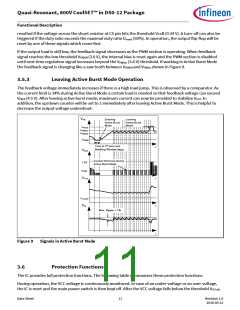
During Active Burst Mode Operation
After entering the Active Burst Mode the feedback voltage rises as VOUT starts to decrease due to the inactive
PWM section. One comparator observes the feedback signal if the voltage level VFBBOn (3.6 V) is exceeded. In that
case the internal circuit is again activated by the internal bias to start with switching.
Turn-on of the power MOSFET is triggered by the timer. The PWM generator for Active Burst Mode operation
composes of a timer with a fixed frequency of fsB (52 kHz, typical) and an analog comparator. Turn-off is
Data Sheet
10
Revision 1.0
2016-05-12

 INFINEON [ Infineon ]