™
PROFET + 24V
BTT6200-4ESA
Electrical characteristics and parameters
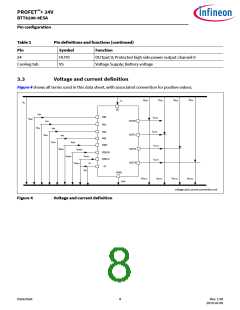
Table 4
Functional range (continued)
TJ = -40°C to 150°C; (unless otherwise specified)
Parameter
Symbol
Values
Typ.
Unit Note or Test
Condition
Number
Min.
Max.
Operating current
All channels active
IGND_4
–
–
–
–
6
9
mA
VIN = 5.5 V
P_4.2.6
VDEN = 5.5 V
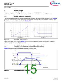
Device in RDS(ON)
VS = 36 V
See Chapter 9.1
6) VS = 36 V
VOUT = 0 V
VIN floating
VDEN floating
TJ ≤ 85 °C
Standby current for whole
device with load (ambient)
IS(OFF)
0.1
0.5
20
–
µA
P_4.2.7
P_4.2.10
P_4.2.8
Maximum standby current for
whole device with load
IS(OFF)_150
–
µA
VS = 36 V
VOUT = 0 V
VIN floating
VDEN floating
TJ = 150 °C
7) VS = 36 V
VOUT = 0 V
Standby current for whole
device with load, diagnostic
active
IS(OFF_DEN)
0.6
mA
VIN floating
VDEN = 5.5 V
Note:
Within the functional range the IC operates as described in the circuit description. The electrical
characteristics are specified within the conditions given in the related electrical characteristics table.
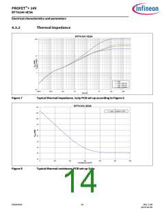
4.3
Thermal resistance
Table 5
Thermal resistance
Parameter
Symbol
Values
Typ.
Unit Note or Test
Condition
Number
Min.
Max.
8)
Junction to case
RthJC
RthJA
–
–
3
–
–
K/W
P_4.3.1
P_4.3.2
8)9)
Junction to ambient
All channels active
28
K/W
6
Test at TJ = -40°C only.
Not subject to production test. Specified by design.
Not subject to production test. Specified by design.
7
8
Datasheet
12
Rev. 1.00
2019-03-09

 INFINEON [ Infineon ]