®
PROFET BTS 740 S2
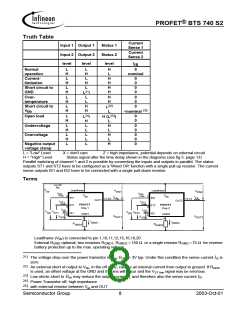
Functional diagram
overvoltage
gate
control
+
current limit
VBB
protection
charge
pump
internal
clamp for
logic
inductive load
OUT1
temperature
sensor
IN1
LOAD
Open load
detection
ESD
ST1
GND1
Current
sense
IS1
GND1
Channel 1
IN2
Control and protection circuit
ST2
of
channel 2
IS2
OUT2
GND2
PROFET
Pin Definitions and Functions
Pin configuration
Pin
Symbol Function
(top view)
1,10,
11,12,
15,16,
19,20
3
V
Positive power supply voltage. Design the
wiring for the simultaneous max. short circuit
currents from channel 1 to 2 and also for low
thermal resistance
bb
V
1 •
2
20 V
19 V
bb
bb
GND1
IN1
ST1
IS1
GND2
IN2
ST2
IS2
bb
3
4
18 OUT1
17 OUT1
IN1
IN2
Input 1,2, activates channel 1,2 in case of
logic high signal
7
5
16 V
17,18
13,14
OUT1
OUT2
Output 1,2, protected high-side power output
of channel 1,2. Both pins of each output have
to be connected in parallel for operation
according ths spec (e.g. kilis). Design the wiring
for the max. short circuit current
bb
6
15 V
bb
7
8
14 OUT2
13 OUT2
9
12 V
bb
4
8
2
6
5
9
ST1
ST2
GND1
GND2
IS1
Diagnostic feedback 1,2 of channel 1,2,
open drain, invers to input level
Ground 1 of chip 1 (channel 1)
V
10
11 V
bb
bb
Ground 2 of chip 2 (channel 2)
Sense current output 1,2; proportional to the
load current, zero in the case of current
limitation of the load current
IS2
Semiconductor Group
2
2003-Oct-01

 INFINEON [ Infineon ]