IDT72T7285/72T7295/72T72105/72T72115 2.5V TeraSync
16,384 x 72, 32,768 x 72, 65,536 x 72, 131,072 x 72
72-BIT FIFO
COMMERCIAL AND INDUSTRIAL
TEMPERATURE RANGES
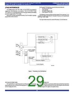
THE INSTRUCTION REGISTER
JTAG INSTRUCTION REGISTER
TheInstructionregisterallowsinstructiontobeseriallyinputintothedevice
whentheTAPcontrollerisintheShift-IRstate.Theinstructionisdecodedto
performthefollowing:
• Selecttestdataregistersthatmayoperatewhiletheinstructioniscurrent.
Theothertestdataregistersshouldnotinterferewithchipoperationandthe
selecteddataregister.
• Definetheserialtestdataregisterpaththatisusedtoshiftdatabetween
TDI and TDO during data register scanning.
The Instruction Register is a 4 bit field (i.e. IR3, IR2, IR1, IR0) to decode
16differentpossibleinstructions. Instructionsaredecodedasfollows.
TheInstructionregisterallowsaninstructiontobeshiftedinseriallyintothe
processor at the rising edge of TCLK.
TheInstructionis usedtoselectthetesttobeperformed,orthetestdata
registertobeaccessed,orboth. Theinstructionshiftedintotheregisterislatched
atthecompletionoftheshiftingprocesswhentheTAPcontrollerisatUpdate-
IRstate.
Theinstructionregistermustcontain4bitinstructionregister-basedcells
whichcanholdinstructiondata. Thesemandatorycellsarelocatednearestthe
serialoutputstheyaretheleastsignificantbits.
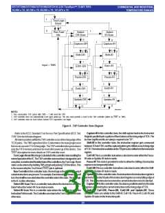
Hex Value Instruction
Function
0x00
0x02
0x01
0x03
0x0F
EXTEST
IDCODE
SelectBoundaryScanRegister
SelectChipIdentificationdataregister
TESTDATAREGISTER
TheTestDataregistercontainsthreetestdataregisters:theBypass,the
Boundary Scan register and Device ID register.
Theseregistersareconnectedinparallelbetweenacommonserialinput
andacommonserialdataoutput.
Thefollowingsectionsprovideabriefdescriptionofeachelement. Fora
completedescription,refertotheIEEEStandardTestAccessPortSpecification
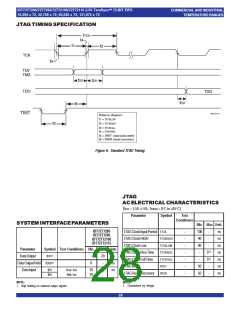
(IEEEStd. 1149.1-1990).
SAMPLE/PRELOAD SelectBoundaryScanRegister
HIGH-IMPEDANCE JTAG
BYPASS
SelectBypassRegister
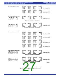
JTAG Instruction Register Decoding
Thefollowingsectionsprovideabriefdescriptionofeachinstruction. For
acompletedescriptionrefertotheIEEEStandardTestAccessPortSpecification
(IEEEStd. 1149.1-1990).
TEST BYPASS REGISTER
EXTEST
TheregisterisusedtoallowtestdatatoflowthroughthedevicefromTDI
toTDO. Itcontainsasinglestageshiftregisterforaminimumlengthinserialpath.
Whenthebypassregisterisselectedbyaninstruction,theshiftregisterstage
is settoa logiczeroonthe risingedge ofTCLKwhenthe TAPcontrolleris in
theCapture-DRstate.
TherequiredEXTESTinstructionplacestheICintoanexternalboundary-
testmodeandselectstheboundary-scanregistertobeconnectedbetweenTDI
andTDO. Duringthis instruction, theboundary-scanregisteris accessedto
drivetestdataoff-chipviatheboundaryoutputsandreceivetestdataoff-chip
viatheboundaryinputs.Assuch,theEXTESTinstructionistheworkhorseof
IEEE.Std1149.1,providingforprobe-lesstestingofsolder-jointopens/shorts
andoflogicclusterfunction.
The operation of the bypass register should not have any effect on the
operationofthedeviceinresponsetotheBYPASSinstruction.
IDCODE
THE BOUNDARY-SCAN REGISTER
TheoptionalIDCODEinstructionallowstheICtoremaininitsfunctionalmode
andselectstheoptionaldeviceidentificationregistertobeconnectedbetween
TDIandTDO.Thedeviceidentificationregisterisa32-bitshiftregistercontaining
information regarding the IC manufacturer, device type, and version code.
Accessingthedeviceidentificationregisterdoesnotinterferewiththeoperation
oftheIC.Also,accesstothedeviceidentificationregistershouldbeimmediately
available,viaaTAPdata-scanoperation,afterpower-upoftheICorafterthe
TAPhasbeenresetusingtheoptionalTRSTpinorbyotherwisemovingtothe
Test-Logic-Resetstate.
TheBoundaryScanRegisterallowsserialdataTDIbeloadedintoorread
outoftheprocessorinput/outputports. TheBoundaryScanRegisterisapart
oftheIEEE1149.1-1990StandardJTAGImplementation.
THE DEVICE IDENTIFICATION REGISTER
The Device IdentificationRegisteris a ReadOnly32-bitregisterusedto
specify the manufacturer, part number and version of the processor to be
determinedthroughtheTAPinresponsetotheIDCODEinstruction.
IDT JEDEC ID number is 0xB3. This translates to 0x33 when the parity
is droppedinthe11-bitManufacturerIDfield.
SAMPLE/PRELOAD
For the IDT72T7285/72T7295/72T72105/72T72115, the Part Number
fieldcontainsthefollowingvalues:
TherequiredSAMPLE/PRELOADinstructionallows theICtoremainina
normalfunctionalmodeandselectstheboundary-scanregistertobeconnected
betweenTDIandTDO.Duringthisinstruction,theboundary-scanregistercan
beaccessedviaadatescanoperation,totakeasampleofthefunctionaldata
enteringandleavingtheIC.Thisinstructionisalsousedtopreloadtestdatainto
theboundary-scanregisterbeforeloadinganEXTESTinstruction.
Device
Part# Field
0493
IDT72T7285
IDT72T7295
IDT72T72105
IDT72T72115
0492
HIGH-IMPEDANCE
0491
TheoptionalHigh-Impedanceinstructionsetsalloutputs(includingtwo-state
aswellasthree-statetypes)ofanICtoadisabled(high-impedance)stateand
selects the one-bit bypass register to be connected between TDI and TDO.
Duringthisinstruction,datacanbeshiftedthroughthebypassregisterfromTDI
toTDOwithoutaffectingtheconditionoftheICoutputs.
0490
31(MSB)
28 27
12 11
1 0(LSB)
BYPASS
Version (4 bits) Part Number (16-bit) Manufacturer ID (11-bit)
The required BYPASS instruction allows the IC to remain in a normal
functionalmodeandselectstheone-bitbypassregistertobeconnectedbetween
TDI and TDO. The BYPASS instruction allows serial data to be transferred
throughtheICfromTDItoTDOwithoutaffectingtheoperationoftheIC.
0X0
0X33
1
IDT72T7285/95/105/115JTAGDeviceIdentificationRegister
31

 IDT [ INTEGRATED DEVICE TECHNOLOGY ]