IDT72T7285/72T7295/72T72105/72T72115 2.5V TeraSync
16,384 x 72, 32,768 x 72, 65,536 x 72, 131,072 x 72
72-BIT FIFO
COMMERCIAL AND INDUSTRIAL
TEMPERATURE RANGES
1
Test-Logic
Reset
0
1
Select-
IR-Scan
0
1
1
Run-Test/
Idle
Select-
DR-Scan
0
0
1
1
Capture-DR
Capture-IR
0
0
0
0
Shift-DR
Shift-IR
1
1
1
1
Input = TMS
Exit1-IR
EXit1-DR
0
0
0
0
Pause-DR
Pause-IR
1
1
Exit2-IR
Exit2-DR
0
0
1
1
Update-DR
Update-IR
1
0
1
0
5994 drw13
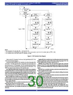
NOTES:
1. Five consecutive TCK cycles with TMS = 1 will reset the TAP.
2. TAP controller does not automatically reset upon power-up. The user must provide a reset to the TAP controller (either by TRST or TMS).
3. TAP controller must be reset before normal FIFO operations can begin.
Figure 8. TAP Controller State Diagram
Capture-IRInthiscontrollerstate,theshiftregisterbankintheInstruction
RegisterparallelloadsapatternoffixedvaluesontherisingedgeofTCK.The
lasttwosignificantbits arealways requiredtobe“01”.
Shift-IR In this controller state, the instruction register gets connected
betweenTDIandTDO,andthecapturedpatterngetsshiftedoneachrisingedge
ofTCK.TheinstructionavailableontheTDIpinisalsoshiftedintotheinstruction
register.
Exit1-IRThisisacontrollerstatewhereadecisiontoentereitherthePause-
IRstateorUpdate-IRstateismade.
Pause-IRThis state is providedinordertoallowthe shiftingofinstruction
registertobetemporarilyhalted.
Exit2-DRThisisacontrollerstatewhereadecisiontoentereithertheShift-
IRstateorUpdate-IRstateismade.
Update-IRInthiscontrollerstate,theinstructionintheinstructionregisteris
latchedintothelatchbankoftheInstructionRegisteroneveryfallingedgeof
TCK.Thisinstructionalsobecomesthecurrentinstructiononceitislatched.
Capture-DRInthiscontrollerstate,thedataisparallelloadedintothedata
registersselectedbythecurrentinstructionontherisingedgeofTCK.
Shift-DR, Exit1-DR, Pause-DR, Exit2-DR and Update-DR These
controllerstates are similartothe Shift-IR, Exit1-IR, Pause-IR, Exit2-IRand
Update-IRstatesintheInstructionpath.
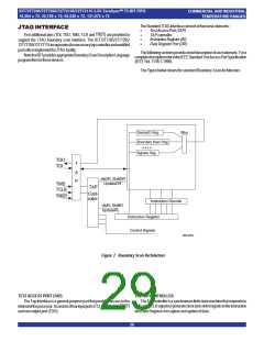
Refer to the IEEE Standard Test Access Port Specification (IEEE Std.
1149.1)forthefullstatediagram
AllstatetransitionswithintheTAPcontrolleroccurattherisingedgeofthe
TCLKpulse. TheTMSsignallevel(0or1)determinesthestateprogression
thatoccursoneachTCLKrisingedge. TheTAPcontrollertakesprecedence
overtheFIFOmemoryandmustberesetafterpowerupofthedevice. See
TRSTdescriptionformoredetailsonTAPcontrollerreset.
Test-Logic-ResetAlltestlogicisdisabledinthiscontrollerstateenablingthe
normaloperationoftheIC.TheTAPcontrollerstatemachineisdesignedinsuch
awaythat,nomatterwhattheinitialstateofthecontrolleris,theTest-Logic-Reset
statecanbeenteredbyholdingTMSathighandpulsingTCKfivetimes.This
is the reason why the Test Reset (TRST) pin is optional.
Run-Test-IdleInthiscontrollerstate,thetestlogicintheICisactiveonlyif
certaininstructionsarepresent.Forexample,ifaninstructionactivatestheself
test,thenitwillbeexecutedwhenthecontrollerentersthisstate.Thetestlogic
intheICis idles otherwise.
Select-DR-ScanThis is a controllerstate where the decisiontoenterthe
DataPathortheSelect-IR-Scanstateismade.
Select-IR-Scan This is a controller state where the decision to enter the
InstructionPathismade.TheControllercanreturntotheTest-Logic-Resetstate
otherwise.
30

 IDT [ INTEGRATED DEVICE TECHNOLOGY ]