IDT72T7285/72T7295/72T72105/72T72115 2.5V TeraSync
16,384 x 72, 32,768 x 72, 65,536 x 72, 131,072 x 72
72-BIT FIFO
COMMERCIAL AND INDUSTRIAL
TEMPERATURE RANGES
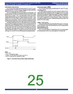
Asynchronous operationofthereadportwillbeselected. DuringAsynchro-
nousoperationofthereadporttheRCLKinputbecomesRDinput,thisisthe
Asynchronousreadstrobeinput.ArisingedgeonRDwillreaddatafromthe
FIFO via the output register and Qn port. (REN must be tied LOW during
Asynchronous operationofthe readport).
The OE input provides three-state control of the Qn output bus, in an
asynchronousmanner.(RCS,providesthree-statecontrolofthereadportin
Synchronousmode).
SIGNALDESCRIPTION
INPUTS:
DATA IN (D0 - Dn)
Datainputsfor72-bitwidedata(D0 -D71),datainputsfor36-bitwidedata
(D0 - D35) or data inputs for 18-bit wide data (D0 - D17).
CONTROLS:
WhenthereadportisconfiguredforAsynchronousoperationthedevice
mustbeoperatingonIDTstandardmode,FWFTmodeisnotpermissibleifthe
readportisAsynchronous.TheEmptyFlag(EF)operatesinanAsynchronous
manner,thatis,theemptyflagwillbeupdatedbasedonbothareadoperation
andawriteoperation.Refertofigures32,33,34and35forrelevanttimingand
operationalwaveforms.
MASTER RESET ( MRS )
AMasterResetisaccomplishedwhenevertheMRSinputistakentoaLOW
state.Thisoperationsetstheinternalreadandwritepointerstothefirstlocation
oftheRAMarray.PAEwill goLOW, PAFwillgoHIGH,and HFwillgoHIGH.
If FWFT/SI is LOW during Master Reset then the IDT Standard mode,
along with EF and FF are selected. EF will go LOW and FF will go HIGH. If
FWFT/SIisHIGH,thentheFirstWordFallThroughmode(FWFT),alongwith
IR and OR, are selected. OR will go HIGH and IR will go LOW.
AllcontrolsettingssuchasOW,IW,BM,BE,RM,PFMandIParedefined
duringtheMasterResetcycle.
RETRANSMIT (RT)
The Retransmit (RT) input is used in conjunction with the MARK input,
togethertheyprovideameansbywhichdatapreviouslyreadoutoftheFIFO
canberereadanynumberoftimes.Ifretransmitoperationhasbeenselected
(i.e.theMARKinputisHIGH),arisingedgeonRCLKwhileRTisLOWwillreset
thereadpointerbacktothememorylocationsetbytheuserviatheMARKinput.
IfIDTstandardmodehasbeenselectedtheEFflagwillgoLOWandremain
LOWforthe time thatRT is heldLOW. RT canbe heldLOWforanynumber
ofRCLKcycles,thereadpointerbeingresettothemarkedlocation.Thenext
risingedge ofRCLKafterRT has returnedHIGH, willcause EFtogoHIGH,
allowingreadoperationstobeperformedontheFIFO.Thenextreadoperation
willaccessdatafromthe‘marked’memorylocation.
Subsequentretransmitoperationsmaybeperformed,eachtimetheread
pointerreturningtothe‘marked’location.SeeFigure18,RetransmitfromMark
(IDTStandardmode)forthe relevanttimingdiagram.
IfFWFTmodehasbeenselectedtheORflagwillgoHIGHandremainHIGH
forthetimethatRTisheldLOW.RTcanbeheldLOWforanynumberofRCLK
cycles,thereadpointerbeingresettothe‘marked’location.ThenextRCLK
risingedgeafterRThasreturnedHIGH,willcauseORtogoLOWanddueto
FWFToperation,thecontentsofthemarkedmemorylocationwillbeloadedonto
the output register, a read operation being required for all subsequent data
reads.
DuringaMasterReset,theoutputregisterisinitializedtoallzeroes.AMaster
Resetisrequiredafterpowerup,beforeawriteoperationcantakeplace.MRS
isasynchronous.
See Figure 9, Master Reset Timing, forthe relevanttimingdiagram.
PARTIAL RESET (PRS)
APartialResetisaccomplishedwheneverthePRS inputistakentoaLOW
state.AsinthecaseoftheMasterReset,theinternalreadandwritepointers
aresettothefirstlocationoftheRAMarray,PAEgoesLOW, PAFgoesHIGH,
and HF goes HIGH.
WhichevermodeisactiveatthetimeofPartialReset,IDTStandardmode
orFirstWordFallThrough,thatmodewillremainselected. IftheIDTStandard
mode is active, then FF will go HIGH and EF will go LOW. If the First Word
Fall Through mode is active, then OR will go HIGH, and IR will go LOW.
Following Partial Reset, all values held in the offset registers remain
unchanged. Theprogrammingmethod(parallelorserial)currentlyactiveat
thetimeofPartialResetisalsoretained. Theoutputregisterisinitializedtoall
zeroes. PRS is asynchronous.
A Partial Reset is useful for resetting the device during the course of
operation,whenreprogrammingprogrammableflagoffsetsettingsmaynotbe
convenient.
Subsequentretransmitoperationsmaybeperformedeachtimetheread
pointerreturningtothe‘marked’location.SeeFigure19,RetransmitfromMark
(FWFTmode)forthe relevanttimingdiagram.
See Figure 10, PartialResetTiming, forthe relevanttimingdiagram.
MARK
ASYNCHRONOUS WRITE (ASYW)
TheMARKinputisusedtoselectRetransmitmodeofoperation.AnRCLK
rising edge while MARK is HIGH will mark the memory location of the data
currently present on the output register, the device will also be placed into
retransmitmode.Note,fortheIDT72T7285/72T7295/72T72105,theremust
beaminimumof128bytesofdatabetweenthewritepointerandreadpointer
whentheMARKisasserted.FortheIDT72T72115,theremustbeaminimum
of256bytesofdatabetweenthewritepointerandreadpointerwhentheMARK
isasserted.Remember,8(x9)bytes=4(x18)words=2(x36)words=1(x72)
word.Also,oncetheMARKisset,thewritepointerwillnotincrementpastthe
“marked”locationuntiltheMARKisdeasserted.Thisprevents“overwriting”
ofretransmitdata.
TheMARKinputmustremainHIGHduringthewholeperiodofretransmit
mode,afallingedgeofRCLKwhileMARKis LOWwilltakethedeviceoutof
retransmitmodeandintonormalmode.AnynumberofMARKlocationscanbe
setduringFIFOoperation,onlythelastmarkedlocationtakingeffect.Oncea
marklocationhasbeensetthewritepointercannotbeincrementedpastthis
ThewriteportcanbeconfiguredforeitherSynchronousorAsynchronous
mode of operation. If during Master Reset the ASYW input is LOW, then
Asynchronousoperationofthewriteportwillbeselected.DuringAsynchro-
nousoperationofthewriteporttheWCLKinputbecomesWRinput,thisisthe
Asynchronouswritestrobeinput.ArisingedgeonWRwillwritedatapresent
ontheDninputsintotheFIFO.(WENmustbetiedLOWwhenusingthewrite
portinAsynchronous mode).
WhenthewriteportisconfiguredforAsynchronousoperationthefullflag
(FF)operatesinanasynchronousmanner,thatis,thefullflagwillbeupdated
based in both a write operation and read operation. Note, if Asynchronous
modeis selected,FWFTis notpermissable.RefertoFigures 30,31,34and
35forrelevanttimingandoperationalwaveforms.
ASYNCHRONOUS READ (ASYR)
ThereadportcanbeconfiguredforeitherSynchronousorAsynchronous
mode of operation. If during a Master Reset the ASYR input is LOW, then
21

 IDT [ INTEGRATED DEVICE TECHNOLOGY ]