IDT72T7285/72T7295/72T72105/72T72115 2.5V TeraSync
16,384 x 72, 32,768 x 72, 65,536 x 72, 131,072 x 72
72-BIT FIFO
COMMERCIAL AND INDUSTRIAL
TEMPERATURE RANGES
intoahighimpedancestate.DuringMasteroraPartialResettheOEistheonly LOAD (LD)
inputthatcanplacetheoutputbusQn,intoHigh-Impedance.DuringResetthe
RCS inputcanbe HIGHorLOW, ithas noeffectonthe Qnoutputs.
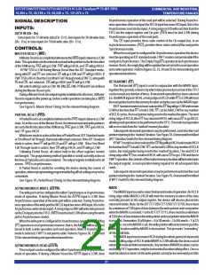
Thisisadualpurposepin. DuringMasterReset,thestateoftheLDinput,
alongwithFSEL0andFSEL1,determinesoneofeightdefaultoffsetvaluesfor
thePAEandPAFflags,alongwiththemethodbywhichtheseoffsetregisters
canbeprogrammed,parallelorserial(seeTable2). AfterMasterReset,LD
READ CHIP SELECT ( RCS )
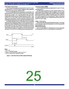
The Read Chip Select input provides synchronous control of the Read enableswriteoperationstoandreadoperationsfromtheoffsetregisters.Only
outputport. WhenRCSgoesLOW,thenextrisingedgeofRCLKcausesthe theoffsetloadingmethodcurrentlyselectedcanbeusedtowritetotheregisters.
QnoutputstogototheLow-Impedancestate. WhenRCSgoesHIGH,thenext Offsetregisters canbereadonlyinparallel.
RCLKrisingedgecausestheQnoutputstoreturntoHIGHZ.DuringaMaster
AfterMasterReset,theLDpinisusedtoactivatetheprogrammingprocess
orPartialResettheRCSinputhasnoeffectontheQnoutputbus,OEistheonly oftheflagoffsetvaluesPAEandPAF.PullingLDLOWwillbeginaserialloading
inputthatprovidesHigh-ImpedancecontroloftheQnoutputs.IfOEisLOWthe or parallel load or read of these offset values. THIS PIN MUST BE HIGH
QndataoutputswillbeLow-ImpedanceregardlessofRCSuntilthefirstrising AFTERMASTERRESETTOWRITEORREADDATATO/FROMTHEFIFO
edgeofRCLKafteraResetiscomplete.ThenifRCSisHIGHthedataoutputs MEMORY.
willgotoHigh-Impedance.
TheRCSinputdoesnoteffecttheoperationoftheflags. Forexample,when BUS-MATCHING (BM, IW, OW)
thefirstwordiswrittentoanemptyFIFO,theEFwillstillgofromLOWtoHIGH
based on a rising edge of RCLK, regardless of the state of the RCS input.
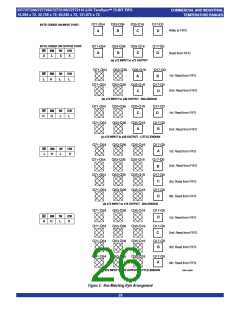
ThepinsBM,IWandOWareusedtodefinetheinputandoutputbuswidths.
DuringMasterReset,thestateofthesepinsisusedtoconfigurethedevicebus
Also,whenoperatingtheFIFOinFWFTmodethefirstwordwrittentoan sizes. SeeTable1forcontrolsettings. Allflagswilloperateontheword/byte
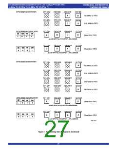
emptyFIFOwillstillbeclockedthroughtotheoutputregisterbasedonRCLK, sizeboundaryasdefinedbytheselectionofbuswidth.SeeFigure5forBus-
regardlessofthestateofRCS.Forthisreasontheusermusttakecarewhen MatchingByteArrangement.
adatawordiswrittentoanemptyFIFOinFWFTmode.IfRCSisdisabledwhen
anemptyFIFOiswritteninto,thefirstwordwillfallthroughtotheoutputregister, BIG-ENDIAN/LITTLE-ENDIAN ( BE )
butwillnotbeavailableontheQnoutputswhichareinHIGH-Z.Theusermust
During Master Reset, a LOW on BE will select Big-Endian operation. A
takeRCSactiveLOWtoaccessthisfirstword,placetheoutputbusinLOW-Z. HIGHonBEduringMasterResetwillselectLittle-Endianformat.Thisfunction
RENmustremaindisabledHIGHforatleastonecycleafterRCShasgoneLOW. isusefulwhenthefollowinginputtooutputbuswidthsareimplemented:x72to
ArisingedgeofRCLKwithRCSandRENactiveLOW,willreadoutthenext x36, x72 to x18, x36 to x72 and x18 to x72. If Big-Endian mode is selected,
word. Care mustbe takensoas nottolose the firstwordwrittentoanempty thenthemostsignificantbyte(word)ofthelongwordwrittenintotheFIFOwill
FIFOwhenRCSisHIGH.RefertoFigure17,RCSandRENReadOperation bereadoutoftheFIFOfirst,followedbytheleastsignificantbyte.IfLittle-Endian
(FWFT Mode). The RCS pin must also be active (LOW) in order to perform formatisselected,thentheleastsignificantbyteofthelongwordwrittenintothe
aRetransmit. SeeFigure13forReadCycleandReadChipSelectTiming(IDT FIFO will be read out first, followed by the most significant byte. The mode
StandardMode). SeeFigure16forReadCycleandReadChipSelectTiming desiredisconfiguredduringmasterresetbythestateoftheBig-Endian(BE)
(First Word Fall Through Mode).
pin. See Figure 5 for Bus-Matching Byte Arrangement.
IfAsynchronousoperationoftheReadporthasbeenselected,thenRCS
mustbeheldactive,(tiedLOW).OEprovidesthree-statecontrolofQn.
PROGRAMMABLEFLAGMODE(PFM)
DuringMasterReset,aLOWonPFMwillselectAsynchronousProgram-
mable flagtimingmode. AHIGHonPFMwillselectSynchronous Program-
WRITE PORT HSTL SELECT (WHSTL)
Thecontrolinputs,datainputsandflagoutputsassociatedwiththewriteport mableflagtimingmode.IfasynchronousPAF/PAEconfigurationisselected
canbesetuptobeeitherHSTLorLVTTL.IfWHSTLisHIGHduringtheMaster (PFM, LOW during MRS), the PAE is asserted LOW on the LOW-to-HIGH
Reset,thenHSTLoperationofthewriteportwillbeselected.IfWHSTLisLOW transition of RCLK. PAE is reset to HIGH on the LOW-to-HIGH transition of
atMasterReset,thenLVTTLwillbeselected.
WCLK.Similarly,thePAFisassertedLOWontheLOW-to-HIGHtransitionof
TheinputsandoutputsassociatedwiththewriteportarelistedinTable5. WCLKandPAF is resettoHIGHontheLOW-to-HIGHtransitionofRCLK.
If synchronous PAE/PAF configuration is selected (PFM, HIGH during
READ PORT HSTL SELECT (RHSTL)
MRS),thePAEisassertedandupdatedontherisingedgeofRCLKonlyand
Thecontrolinputs,datainputsandflagoutputsassociatedwiththereadport notWCLK.Similarly,PAFisassertedandupdatedontherisingedgeofWCLK
canbesetuptobeeitherHSTLorLVTTL.IfRHSTLisHIGHduringtheMaster only and not RCLK. The mode desired is configured during master reset by
Reset,thenHSTLoperationofthereadportwillbeselected.IfRHSTLisLOW thestateoftheProgrammableFlagMode(PFM)pin.
atMasterReset,thenLVTTLwillbeselectedforthereadport,thenechoclock
and echo read enable will not be provided.
INTERSPERSED PARITY (IP)
TheinputsandoutputsassociatedwiththereadportarelistedinTable5.
During Master Reset, a LOW on IP will select Non-Interspersed Parity
mode.A HIGHwillselectInterspersedParitymode.TheIPbitfunctionallows
theusertoselecttheparitybitinthewordloadedintotheparallelport(D0-Dn)
SYSTEM HSTL SELECT (SHSTL)
Allinputsnotassociatedwiththewriteandreadportcanbesetuptobeeither whenprogrammingtheflagoffsets.IfInterspersedParitymodeisselected,then
HSTLorLVTTL.IfSHSTLisHIGHduringMasterReset,thenHSTLoperation theFIFOwillassumethattheparitybitsarelocatedinbitpositionD8,D17,D26,
ofalltheinputsnotassociatedwiththewriteandreadportwillbeselected.If D35,D44,D53,D62andD71duringtheparallelprogrammingoftheflagoffsets.
SHSTL is LOW at Master Reset, then LVTTL will be selected. The inputs If Non-Interspersed Parity mode is selected, then D8, D17 and D28 are is
associatedwithSHSTLare listedinTable 5.
assumed to be valid bits and D64, D65, D66, D67, D68, D69, D70 and D71 are
ignored. IPmodeisselectedduring MasterResetbythestateoftheIPinputpin.
23

 IDT [ INTEGRATED DEVICE TECHNOLOGY ]