IDT70V5388/78
3.3V 64/32K x 18 Synchronous FourPort™ Static RAM
Industrial and Commercial Temperature Ranges
Counter-MaskRegister
CNTINT
Load
Counter-Mask
Register = FF
H
0 0
0's 0 1 1 1 1 1 1 1 1
STEP 1
A
15(2)
A14
A8
A7
A6
A5
A4
A3
A1 A0
A2
Masked Address
Counter Address
Load
Address
Counter = FD
STEP 2
H
H
L
0 0
0's
X's
0 1 1 1 1 1 1 0 1
A
15(2)
A14
A8
A7
A6
A5
A4
A3
A1 A0
A2
Max
Address
Register
STEP 3
STEP 4
,
X X
1 1 1 1 1 1 1
1
X
A
15(2)
A14
A8 A7 A6 A5 A4 A3 A2 A1 A0
Max + 1
Address
Register
X X
X's X 0 0 0 0 0 0 0 0
A
15(2)
A14
A8 A7 A6 A5 A4 A3 A2 A1 A0
5649 drw 23
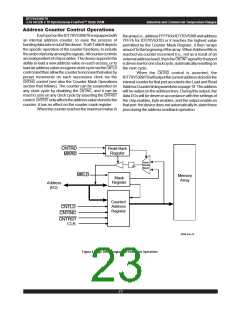
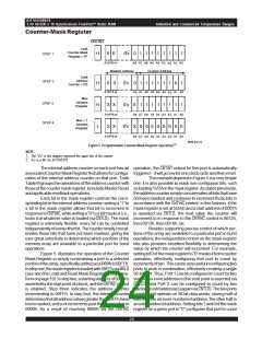
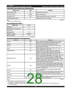
Figure 5. Programmable Counter-Mask Register Operation(1)
NOTE:
1. The "X's" in this diagram represent the upper bits of the counter.
2. A15 is a NC for IDT70V5378.
The internal address counter on each port has an operation, the CNTINT output for this port is automatically
associatedCounterMaskRegisterthatallowsforconfigu- triggered – it will go low for one clock cycle and then reset.
ration of the internal address counter on that port. Truth
TheexampledepictedinFigure 5isaverysimple
TableIIIgroupstheoperationsoftheaddresscounterwith one: it is also possible to mask non-contiguous bits, such
thoseofthecountermaskregister,toincludeMasterReset asloading5555hinthemaskregister.Asstatedpreviously,
andapplicablereadbackoperations.
theaddresscountersimplyconcatenatesallbitsthathave
Each bit in the mask register controls the corre- not been masked and continues to increment those bits in
spondingbitintheinternaladdresscounter:writinga“1”to accordance with the CNTINC control: in this fashion, if the
a bit in the mask register allows that bit to increment in mask register is set at 5555h and a start address of 0007h
responsetoCNTINC,whilewritinga“0”toabitmasksit(i.e., is asserted via CNTLD, the next value the counter will
locks it at whatever value is loaded via CNTLD). The mask increment to in response to the CNTINC control is 0012h,
register is extremely flexible: every bit can be controlled then 0013h, then 0016h, etc.
independentlyofeveryotherbit.Thecountersimplyconcat-
Besides supporting precise control of which por-
enates those bits that have not been masked, giving the tions of the array are available to a particular port in burst
user great selectivity in determining which portions of the operations, the independent control on the mask register
memory array are available to a particular port for burst bits also provides excellent flexibility in determining the
operations.
value by which the counter will increment. For example,
Figure 5 illustrates the operation of the Counter settingbit0ofthemaskregisterto“0”masksitfromcounter
Mask Register in simply constraining a port to a selected operation, effectively configuring that port to count by
portionofthearray,specificallyaddresses0000hto00FFh. incrementsoftwo.Thiscanbeveryusefulinconfiguringtwo
Instepone,themaskregisterisloadedwith00FFhviaMKLD ports to work in combination, effectively creating a single
(see also the Load and Read Mask Register timing wave- 36-bit port. Thus, Port 1 can be configured to count by two
formonpage19).Insteptwo,astartingaddressof00FDis starting on even addresses (the start point is asserted via
assertedforthestartpointofaburst,andtheCNTINC control CNTLD), and Port 2 can be configured to count by two
is enabled. Step three indicates the address counter startingonoddaddresses(againviaCNTLD).Thetwoports
incrementing to 00FFh. In step four, the internal counter together will operate on 36-bit data words, storing half of
determinesthatalladdressvaluesgreaterthan00FFhhave eachwordinaneven-numberedaddress, theotherhalfin
beenmasked, andsoitincrementspastthis‘max’valueto anodd-numberedaddress.Settingbits1and0ofthemask
0000h. As a result of reaching 0000h via the CNTINC register on a given port to “0” configures that port to count
24

 IDT [ INTEGRATED DEVICE TECHNOLOGY ]