IDT70V5388/78
3.3V 64/32K x 18 Synchronous FourPort™ Static RAM
Industrial and Commercial Temperature Ranges
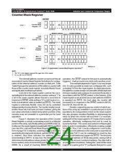
in increments of four: masking bits 2, 1, and 0 configures
that port to count in increments of eight, and so on. The
ability to set the increments by which the counters will
advance gives the user the ability to interleave memory
operationsamongtheports, minimizingtheconcernsthat
a given address might be written by more than one port at
any given point in time (an operation that would have
indeterminateresults).
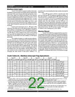
whilea"1"indicatesthatthememoryarraypassed.Therest
of the MRR contains the total number of failed read cycles
in the entire MBIST sequence.
The IDT70V5388/78 MBIST function has been
supplemented with the ability for the user to force a failure
reportfromthedevice. Thisallowstheusertheflexibilityof
validating the MBIST function itself, by verifying that the
deviceisabletoreportfaultsaswellaspassingresults.The
two modes of operation, normal MBIST testing and forced
error reporting, are controlled via the JTAG TAP interface
usingtheinstructionPROGRAM_MBIST_MODE_SELECT.
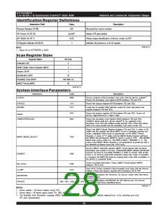
For further detail, please refer to the System Interface
Parameters table on page 28.
TheMBISTfunctionexecutesoncetheRUNBIST
instructionisinputviatheJTAGinterface.TheentireMBIST
test will be performed with a deterministic number of TCK
cycles depending on the TCK and CLKMBIST frequency.
This can be calculated by using the following formula:
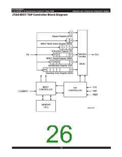
JTAGSupport
The IDT70V5388/78 provides a serial boundary
scan test access port . The JTAG tables starting on page
29providethespecificdetailsfortheJTAGimplementation
on this device.
The IDT70V5388/78 executes a JTAG test logic
resetuponpower-up. Thispower-upresetwillinitializethe
TAP controller and MBIST controller. In most power
environmentsnofurtheractionisrequired. However,ifthe
user has any concern about the system’s voltage states
during power-up, then the user can use the optional TRST
input as part of a board’s power on reset sequence. The
TRST pinalsoprovidesanalternatemeansofresettingthe
JTAG test logic when required, and is available for use by
externalJTAGcontrollersasanasynchronousresetsignal.
IftheuserdoesnotplantorelyontheoptionalTRST pin,but
wantstouseJTAGfunctionality,theTRST pinshouldeither
betiedHIGH(preferredimplementation)orleftfloating.
IfJTAGoperationsarenotdesired,theuserhasa
tCYC[CLKMBIST]
tCYC[TCK]
x m + SPC, where:
tCYC =
tCYC is the total number of TCK cycles required to run
MBIST.
SPC is the synchronization padding cycles (typically 4-6
cycles, to accommodate state machine overhead, turn-
around cycles, etc.)
number of options for disabling the JTAG functions. One
wouldbetosimplytieTCKLOW,leavingallotherJTAGpins
floating (alternatively, TDI and TMS could be tied HIGH).
Since the device executes a JTAG reset upon power-up:
withTCKtiedLOW,nofurtherclockingoftheTAPwilloccur
and no JTAG operations will take place. Alternatively, the
user can opt to tie TRST LOW(eitherinlieuoforinaddition
to tying TCK LOW) and the TAP will be locked in a reset
condition, blocking all JTAG operations.
misaconstantthatrepresentsthenumberofreadandwrite
operations required to run the internal MBIST algorithms
(14,811,136)forbothIDT70V5388andIDT70V5378.
MemoryBuilt-In-TestOperations
Go-NoGo Testing
The IDT70V5388/78 is equipped with a self-test
functionthatcanberunbytheuserastheresultofasingle
instruction, implemented via the JTAG TAP interface. If
multipleFourPortdevicesareusedonthesameboard,all
can execute MBIST simultaneously, facilitating board
checkout.
The MBIST function executes a Go-NoGo test
withinthedevice,whichthencapturespass-failinformation
and failure count in a special register called the MBIST
Result Register (MRR). Upon completion of the test, the
MRRcanbescannedoutviatheJTAGinterface,usingthe
internalscanoperation. BitzerooftheMRR(MRR[0])isa
don'tcare.BitoneoftheMRR(MRR[1])indicatesthepass/
fail status: a "0" indicates some sort of failure was noted,
25
6.42

 IDT [ INTEGRATED DEVICE TECHNOLOGY ]