IDT70825S/L
High-Speed 8K x 16 Sequential Access Random Access Memory
Industrial and Commercial Temperature Ranges
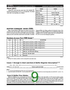
Reset (RST)
Register
Contents
0
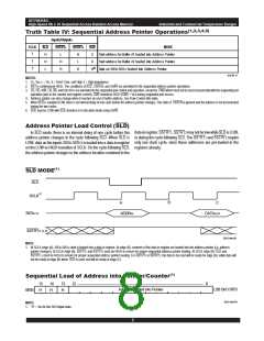
Setting RST LOW resets the control state of the SARAM. RST
functions asynchronously of SCLK, (i.e. not registered). The default
states after a reset operation are as follows:
Address Pointer
Cleared to High State
BUFFER CHAINING
EOB Flags
Buffer Flow Mode
Start Address Buffer #1
End Address Buffer #1
Start Address Buffer #2
End Address Buffer #2
Registered State
0
(1)
4095
4096
8191
(4K)
(4K+1)
(8K)
SCE = VIH, SR/W = VIL
3016 tbl 15
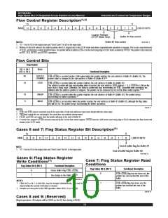
BUFFER COMMAND MODE (CMD)
Buffer Command Mode (CMD) allows the random access port to Command Mode also allows reading and clearing the status of the
control the state of the two buffers. Address pins A0-A2 and I/O pins I/ EOBflags.SevendifferentCMDcasesareavailabledependingonthe
O0-I/O12 are used to access the start of buffer and the end of buffer conditions of A0-A2 and R/W. Address bits A3-A12 and data I/O bits
addresses and to set the flow control mode of each buffer. The Buffer I/O13-I/O15 are not used during this operation.
Random Access Port CMD Mode(1)
Case #
A
2
-A
0
R/W
0 (1)
0 (1)
0 (1)
0 (1)
0 (1)
0
DESCRIPTIONS
Write (read) the start address of Buffer #1 through I/O -I/O12
Write (read) the end address of Buffer #1 through I/O -I/O12
Write (read) the start address of Buffer #2 through I/O -I/O12
Write (read) the end address of Buffer #2 through I/O -I/O12
Write (read) flow control register.
Write only - clear EOB and/or EOB
1
2
3
4
5
6
7
8
000
001
0
.
0
.
010
0
.
011
0
.
100
101
1
2 flag.
101
1
Read only - flag status register.
(Reserved)
110/111
(X)
3016 tbl 16
NOTES:
1. R/W input "0(1)" indicates a write(0) or read(1) occurring with the same address input.
Cases 1 through 4: Start and End of Buffer Register Description(1,2)
15
14
13
12 ------------------------------------------------------------------------------------------------------------ 0
Address Loaded into Buffer
LSB I/O BITS
MSB
H
H
H
3016 drw 10
NOTES:
1. "H" = VOH for I/O in the output state and "Don't Cares" for I/O in the input state.
2. A write into the buffer occurs when R/W = VIL and a read when R/W = VIH. EOB1/SOB1 and EOB2/SOB2 are chosen through address A0-A2 while CMD = VIL and CE = VIH.
Case 5: Buffer Flow Modes
Within the SARAM, the user can designate one of four buffer flow start address of the other buffer. In STOP mode, the address pointer
modes for each buffer. Each buffer flow mode defines a unique set of stops incrementing after it reaches the end of the buffer. In LINEAR
actions for the sequential port address pointer and EOB flags. In mode, the address pointer ignores the end of buffer address and
BUFFER CHAINING mode, after the address pointer reaches the end increments past it, but sets the EOB flag. MASK mode is the same as
ofthebuffer,itsetsthecorrespondingEOBflagandcontinuesfromthe LINEAR mode except EOB flags are not set.
6.42
9

 IDT [ INTEGRATED DEVICE TECHNOLOGY ]