IDT70825S/L
High-Speed 8K x 16 Sequential Access Random Access Memory
Industrial and Commercial Temperature Ranges
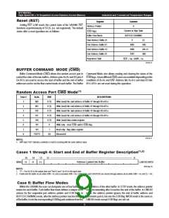
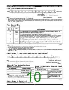
Flow Control Register Description(1,2)
0
15
MSB
H
H
H
H
H
H
H
H
H
H
4
3
2
1
0
LSB I/O BITS
H
Counter Release
(STOP Mode Only)
Buffer #1 flow control
Buffer #2 flow control
3016 drw 11
NOTES:
1. "H" = VOH for I/O in the output state and "Don't Cares"' for I/O in the input state.
2. Writing a 0 into bit 4 releases the address pointer after it is stopped due to the STOP mode and allows sequential write operations to resume. This occurs asynchronously
of SCLK, and therefore caution should be taken. The pointer will be at address EOB+2 on the next rising edge of SCLK that is enabled by CNTEN. The pointer is also released
by RST, SLD, SSTRT1 and SSTRT2 operations.
Flow Control Bits
Flow Control
Bit 1 & Bit 0
(Bit 3 & Bit 2)
Mode
Functional Description
00
01
BUFFER
EOB
1
(EOB2) is asserted (active LOW output) when the pointer matches the end address of Buffer #1 (Buffer #2). The
(1,3)
CHAINING
pointer value is changed to the start address of Buffer #2 (Buffer #1)
STOP
EOB
1
(EOB2) is asserted when the pointer matches the end address of Buffer #1 (Buffer #2).
The address pointer will stop incrementing when it reaches the next address (EOB address + 1), if CNTEN is LOW on the
next clock's rising edge. Otherwise, the address pointer will stop incrementing on EOB. Sequential write operations are
inhibited after the address pointer is stopped. The pointer can be released by bit 4 of the flow control register.(1,2,4)
10
11
LINEAR
MASK
EOB
1
(EOB2) is asserted when the pointer matches the end address of Buffer #1 (Buffer #2). The pointer keeps
incrementing for further operations.(1)
EOB
1
(EOB2) is not asserted when the pointer reaches the end address of Buffer #1 (Buffer #2), although the flag status
bits will be set. The pointer keeps incrementing for further operations.
3016 tbl 17
NOTES:
1. EOB1 and EOB2 may be asserted (set) at the same time, if both end addresses have been loaded with the same value.
2. CMD flow control bits are unchanged, the count does not continue advancement.
3. If EOB1 and EOB2 are equal, then the pointer will jump to the start of Buffer #1.
4. If counter has stopped at EOBx and was released by bit 4 of the flow control register, CNTEN must be LOW on the next rising edge of SCLK otherwise the flow control will
remain in the STOP mode.
Cases 6 and 7: Flag Status Register Bit Description(1)
0
0
15
MSB
H
H
H
H
H
H
H
H
H
H
H
H
H
H
1
LSB I/O BITS
End of buffer flag for Buffer #1
End of buffer flag for Buffer #2
NOTE:
1. "H" = VOH for I/O in the output state and "Don't Cares" for I/O in the input state.
3016 drw 12
Cases 6: Flag Status Register
Write Conditions(1)
Case 7: Flag Status Register Read
Conditions
Flag Status Bit 0, (Bit 1)
Functional Description
Clears Buffer Flag EOB , (EOB
No change to the Buffer Flag.(2)
Flag Status Bit 0, (Bit 1)
Functional Description
0
1
1
2).
0
EOB
1
(EOB2) flag has not been set, the
pointer has notreached the end of the
buffer.
3016 tbl 18
NOTES:
1
EOB
1
(EOB2) flag has been set, the
1. Either bit 0 or bit 1, or both bits, may be changed simultaneously. One may be
cleared while the second is left alone or cleared.
2. Remains as it was prior to the CMD operation, either HIGH (1) or LOW (0).
pointer has reached the end of the
buffer.
3016 tbl 19
Cases 8 and 9: (Reserved)
Illegal operations. All outputs will be HIGH on the I/O bus during a READ.
10

 IDT [ INTEGRATED DEVICE TECHNOLOGY ]