iC-MR 13-BIT S&H SIN/COS
INTERPOLATOR WITH CONTROLLER INTERFACES
Rev A1, Page 33/44
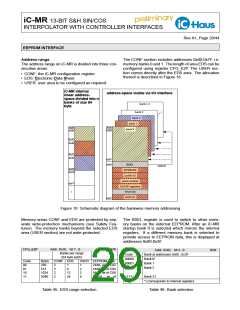
Data sequence shortened format (FULL_CYC = 0)
registers 0x61 and 0x67 are bypassed; only 24 bits of
singleturn and 16 bits of multiturn data are output.
Byte No.
1
2
Data
Status byte
Register
STAT(7:0)
ST(9:2)
Address
0x60
0x62
0x63
0x64
0x65
0x66
0x68
0x69
0x6A
Singleturn Lo byte
Singleturn Mid byte
Singleturn Hi byte
Multiturn Lo byte
Multiturn Mid byte
Life counter
FULL_CYC
Addr. 0x18; bit 5
Function
R/W
3
4
5
ST(17:10)
ST(25:18)
MT(7:0)
Code
0
1
24-bit ST / 16-bit MT
26-bit ST / 24-bit MT
6
7
MT(15:8)
LC(7:0)
8
9
10
11
12
Error byte
ERR(7:0)
TEMP(7:0)
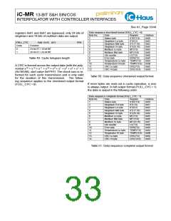
Table 49: Cyclic telegram length
Temperature Lo byte
Temperature Hi byte
CRC Lo byte
TEMP(15:8) 0x6B
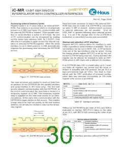
A CRC is formed across the output data (with the poly-
nomial x16 + x14 + x11 + x10 + x9 + x7 + x5 + x3 + x1 + 1
(0x14EAB), start value 0xFFFF). The check sum is re-
formed for each cyclic transmission and is only valid
for the duration of this transmission. The follow-
ing sequence applies to the shortened output format
(FULL_CYC = 0):
CRC(7:0)
CRC(15:8)
0x6C
0x6D
CRC Hi byte
Table 50: Data sequence shortened output format
If more bytes are read out in cyclic operation, a zero
is always output. In full output format (FULL_CYC = 1)
the data is output in the following order:
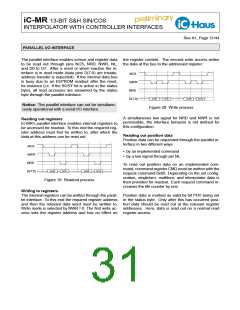
Data sequence complete format (FULL_CYC = 1)
Byte No.
1
2
3
4
5
6
7
Data
Status byte
Register
STAT(7:0)
ST(1:0)
Address
0x60
0x61
0x62
0x63
0x64
0x65
0x66
0x67
0x68
0x69
0x6A
Singleturn Ext byte
Singleturn Lo byte
Singleturn Mid byte
Singleturn Hi byte
Multiturn Lo byte
Multiturn Mid byte
Multiturn Hi byte
Life counter
ST(9:2)
ST(17:10)
ST(25:18)
MT(7:0)
MT(15:8)
MT(23:16)
LC(7:0)
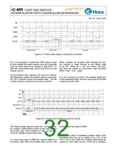
ERR(7:0)
TEMP(7:0)
TEMP(15:8) 0x6B
8
9
10
11
12
13
14
Error byte
Temperature Lo byte
Temperatur Hi byte
CRC Lo byte
CRC(7:0)
CRC(15:8)
0x6C
0x6D
CRC Hi byte
Table 51: Data sequence complete output format

 ICHAUS [ IC-HAUS GMBH ]