iC-MR 13-BIT S&H SIN/COS
INTERPOLATOR WITH CONTROLLER INTERFACES
Rev A1, Page 31/44
PARALLEL I/O INTERFACE
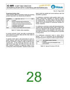
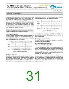
The parallel interface enables sensor and register data the register content. The second write access writes
to be read out through pins NCS, NRD, NWR, NL, the data at the bus to the addressed register.
and D0 to D7. After a reset or when inactive the in-
terface is in read mode (data pins D(7:0) are tristate,
NCS
address transfer is expected). If the internal data bus
is busy due to an EEPROM readout after the reset,
NWR
for instance (i.e. if the BUSY bit is active in the status
byte), all read accesses are answered by the status
byte through the parallel interface.
NRD
ADDR1
DATA1
ADDR2
DATA2
D(7:0)
Notice: The parallel interface can not be simultane-
ously operational with a serial I/O interface.
Figure 20: Write process
A simultaneous low signal for NRD and NWR is not
permissible; the interface behavior is not defined for
this configuration.
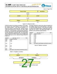
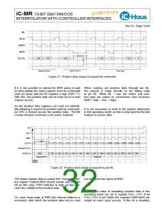
Reading out registers
iC-MR’s parallel interface enables internal registers to
be accessed for readout. To this end the required reg-
ister address must first be written to, after which the
data at this address can be read out.
Reading out position data
Position data can be requested through the parallel in-
terface in two different ways:
NCS
NWR
NRD
• by an implemented command
• by a low signal through pin NL.
To read out position data on an implemented com-
mand, command register CMD must be written with the
request command 0x00. Depending on the set config-
uration, singleturn, multiturn, and interpolator data is
then provided for readout. Each request command in-
creases the life counter by one.
ADDR1
DATA1
ADDR2
DATA2
D(7:0)
Figure 19: Readout process
Writing to registers
The internal registers can be written through the paral- Position data is marked as valid by bit PDV being set
lel interface. To this end the required register address in the status byte. Only after this has occurred posi-
and then the relevant data word must be written to. tion data should be read out at the relevant register
Write mode is selected by NWR = 0. The first write ac- addresses. Here, data is read out on a normal read
cess sets the register address and has no effect on register access.

 ICHAUS [ IC-HAUS GMBH ]