iC-MR 13-BIT S&H SIN/COS
INTERPOLATOR WITH CONTROLLER INTERFACES
Rev A1, Page 37/44
SERIAL I/O INTERFACE: SPI
Register access
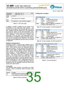
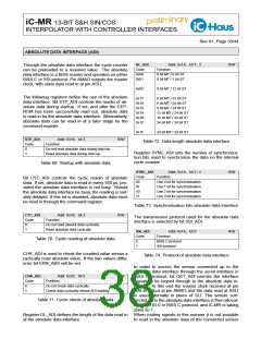
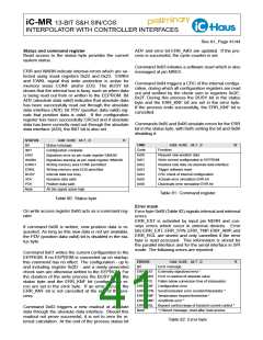
The third byte concludes the transmission, with which
SPI protocol can also be used for communication the register data (WRITEDATA) is written through pin
through the serial interface. Data changes at pins SLI SLI on a register write access. On a register read ac-
and SLO respectively on a falling edge at MAI and is cess the requested register data (READDATA) can be
accepted on a rising edge at MAI. If the internal data read out at pin SLO. To access the command register
bus is busy due to an EEPROM readout after the reset, the protocol can be shortened to two bytes, as the op-
for instance (i.e. if the BUSY bit is active in the status code already contains the command to be executed.
byte), all read accesses are answered by the status
Command
byte through the serial interface in SPI mode.
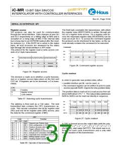
The protocol for the register read or write access con-
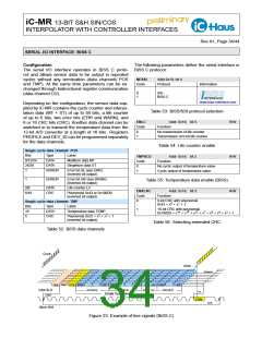
MAI
sists of a 3-byte transmission.
NCS
SLI
OPC
- - -
CYC & x60
- - -
- - -
- - -
MAI
NCS
SLI
SLO
OPC
- - -
CYC & ADR(6:0)
- - -
WRITEDATA
READDATA
Figure 26: Command register access
SLO
Figure 25: Register access
Cyclic readout
The decision is made as to whether a cyclic transmis-
sion or a register access takes place on the first sent
CYC bit. If registers are to be accessed, a 0 is trans-
mitted.
In order to generate new position data, either
• parallel interface pin NL can be used, or
• the command register can be written to prior to cyclic
access (opcode 0x00: request for new position data).
CYC
Code
Function
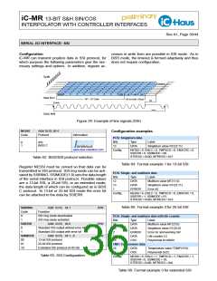
The position data is read out on a read access from ad-
dress 0x60 when CYC = 1. The output data (addresses
0x60 to 0x6D) can be read out directly in sequence.
0
1
Register access
Cyclic readout
Table 67: Selecting cyclic transmission
MAI
The address is then sent as a 7-bit value. The next
transmitted byte contains the OPC transmission op-
code. This opcode comprises one bit for register read
(RD) and one bit for register write (WR) access, plus
the data for the command register (CMD).
NCS
SLI
CYC & x60
- - -
- - -
STATUS
0x60
SLO
ST(1:0)
0x61
...
...
CRC(7:0)
0x6C
CRC(15:8)
0x6D
- - -
ADDR int
OPC
Figure 27: Cyclic readout
Code
Function
–
RD WR CMD
00
00
00
00
00
00
00
00
00
0
0
0
0
0
0
0
0
1
0
0
0
0
0
0
0
1
0
0000 Request new Position data
0001 Write configuration in EEPROM
0010 Readout absolute data interface
0011 Trigger software reset
0100 CRC verification of internal configuration
0101 Activate error simulation ERR bit
0110 Deactivate error simulation ERR bit
0000 Writing register access
A CRC is formed across the output data (with the poly-
nomial x16 + x14 + x11 + x10 + x9 + x7 + x5 + x3 + x1 + 1
(0x14EAB), start value 0xFFFF). The check sum is re-
formed for each cyclic transmission and is only valid
for the duration of this transmission.
0000 Reading register access
Table 68: Opcode of transmission

 ICHAUS [ IC-HAUS GMBH ]