iC-MR 13-BIT S&H SIN/COS
INTERPOLATOR WITH CONTROLLER INTERFACES
Rev A1, Page 30/44
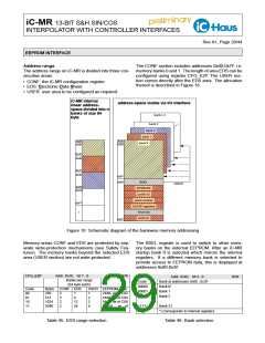
Accessing external memory banks
Read and write accesses to data in the external EEP-
Register banks 2 to 31 store data in an external EEP- ROM may only be made if an EEPROM is connected
ROM. If an address is accessed which is not physically up when iC-MR is started. Autoincrement accesses
present on iC-MR (see Figure 16), communication with to external addresses are not possible. Error bit
the external EEPROM is initiated. If the parallel inter- ERR_KNF is updated following each external access
face or serial interface is active in SPI mode, the end (e.g. it is set if the storage time on the EEPROM is
of I²C communication can be recognized by reading undershot, or cancelled if access was successful).
out the status byte (address 0x60, bit 2 BUSY). Only
after this is it possible to again access the internal reg-
isters or external EEPROM registers. When the serial
Startup and selection of I/O interface
Register INTCFG defines which I/O interface is used.
interface is run in BiSS protocol, iC-MR automatically
Either a parallel or serial interface is available. The se-
requests the processing time necessary for EEPROM
rial interface can be run on BiSS, SSI, or SPI protocol.
Only one of the two interfaces may be active. During
access.
the startup phase register INTCFG is set by the con-
nected EEPROM being read out. During operation the
register can be altered, for example to write an EEP-
ROM which iC-MR starts with a different I/O interface.
If an EEPROM data CRC is invalid (after up to 3 read-
out trials) all registers are zeroed and the serial in-
terface is activated with SSI protocol, but pin SLO is
kept permanently high (at VDD). This state is main-
tained until the CRC verification of renewed configu-
ration data was executed successfully (in SSI mode
register write access is permitted).
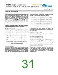
Figure 17: EEPROM read access
Two read accesses are needed to read out data from
an address on the EEPROM (for the parallel interface
and serial interface in SPI mode only). The first read
access initiates communication with the EEPROM; at
the end of communication the read data is stored in a
temporary register on iC-MR. This temporary register
data is supplied on the next read access to an exter-
nal address. At the same time communication with the
EEPROM is again started on this access. This enables
a large area to be read out quickly, as the next readout
address can already be created to read out the tempo-
rary register.
INTCFG
Code
11
Addr. 0x18; bit 7...6
Function
(R/W)
Parallel interface
10
Serial interface with SPI protocol
Invalid value
01
00
Serial interface with BiSS/SSI protocol*
*) Switching BiSS/SSI with register NESSI
Note
Table 47: Interface selection
Without an EEPROM the pin state of SCL and SDA is
evaluated on startup; INTCFG(1) takes on the value
at pin SCL, with INTCFG(0) assuming the value at pin
SDA.
Startup without EEPROM
SCL level
SDA level
Activated interface
1
1
0
0
1
0
1
0
Parallel interface
Serial interface with SPI protocol
Invalid value
Serial interface with BiSS/SSI proto-
col
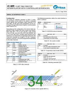
Figure 18: EEPROM write access
Table 48: Interface selection without EEPROM

 ICHAUS [ IC-HAUS GMBH ]