iC-MR 13-BIT S&H SIN/COS
INTERPOLATOR WITH CONTROLLER INTERFACES
Rev A1, Page 35/44
CRCS(15:8)
CRCS(7:0)
Code
Addr. 0x28; bit 7...0
Addr. 0x29; bit 7...0
R/W
Configuration examples
Function
POS: Singleturn data
0x00
Bits
Type
Label
...
Start value for CRC calculation
24
DATA
ERROR
CRC
Singleturn value ST(23:0)
Error nE and warning nW
Polynomial 0x43
0xFF
2
Note
For ENXCRC = ’0’ only CRCS(5:0) is applied.
Table 57: CRC start value
6
Config.
NESSI = 1, ENLC = 0, TMPSCD = 0, ENXCRC = 0,
STRESO = 0x02, MTRESO = 0x7
In addition, bit ENLC enables the life counter to be
transmitted on the single-cycle data channel. The
counter data (6 bits) is sent directly after the nE/nW
bits. Register ENXCRC defines the CRC polynomial
used and the number of CRC bits transmitted. Here,
CRCS allows a free start value to be programmed for
CRC calculation. If the 6-bit CRC is chosen, only
CRCS bits 5 to 0 are used. The temperature can be
transmitted as an additional single-cycle data channel.
This can be controlled by bit TMPSCD. The timeout
is always formed adaptively and thus does not require
configuration.
Table 59: Format example 1 for BiSS profile BP1
POS: Single- and multiturn data
Bits
Type
Label
24
DATA
DATA
ERROR
CRC
Multiturn value MT(23:0)
Singleturn value ST(11:0) & x"000"
Error nE and warning nW
Polynomial 0x43
24
2
6
Config.
NESSI = 1, ENLC = 0, TMPSCD = 0, ENXCRC = 0,
STRESO = 0x0E, MTRESO = 0x0
Table 60: Format example 2 for BiSS profile BP1
Register communication
POS: Single- and multiturn data with life counter
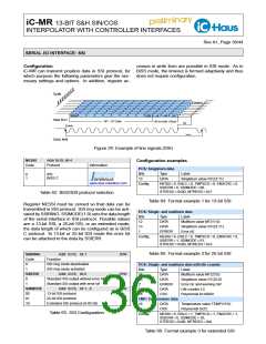
According to BiSS C protocol slave registers are di-
rectly addressed in a reserved address area (0x40 to
0x7F). Other memory areas are addressed dynami-
cally and in blocks. For this purpose BiSS addresses
0x00 to 0x3F target a register bank consisting of 64
bytes, whose physical storage address determines
bank selection n. iC-MR supports up to 32 memory
banks, enabling a 16-kbit EEPROM to be fully ex-
ploited. This means that there is sufficient storage
space for an ID plate (EDS) and OEM data. Page
29 provides information on memory allocation and ad-
dressing through BiSS. If the internal bus is busy in
BiSS C mode (due to a CRC, configuration being writ-
ten to the EEPROM, or absolute data being read out
through the ADI, for example), zeroes are sent on the
single-cycle data channel.
Bits
12
26
2
Type
Label
DATA
DATA
ERROR
DATA
CRC
Multiturn value MT(11:0)
Singleturn value ST(25:0)
Error nE and warning nW
Life counter LC
6
16
Polynomial 0x190D9
TMP: Temperature data
16
DATA
CRC
Temperature value TEMP(15:0)
Polynomial 0x25
5
Config.
NESSI = 1, ENLC = 1, TMPSCD = 1, ENXCRC = 1,
STRESO = 0x00, MTRESO = 0x3
Table 61: Format example 3
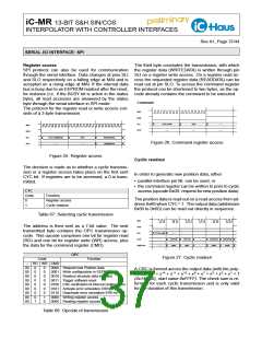
Commands
The following BiSS interface commands are imple-
mented. These commands cannot be listed in the
broadcast.
Opcode
10
Function
Readout new data via absolute data interface
CRC verification of internal configuration
11
Table 58: BiSS commands

 ICHAUS [ IC-HAUS GMBH ]