iC-MR 13-BIT S&H SIN/COS
INTERPOLATOR WITH CONTROLLER INTERFACES
Rev A1, Page 32/44
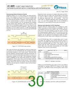
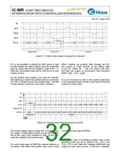
NL
NCS
NWR
NRD
STATUS
0x60
0x00
0x60
0x62
ST
0x63
ST
D(7:0)
Request Position
Wait for PDV=1
Read Data
Figure 21: Position data output at request by command
If it is not possible to extend the NRD pulse to wait When reading out position data through pin NL,
for data validity, the status register must be continually the request is made directly on the falling edge
read out anew until pin D0 supplies a high (PDV = 1). at pin NL. While NL = low, the status and posi-
After this, the position data can be read out on a read tion data are output on consecutive read accesses
register access.
(NRD = high → low → high).
As the position data registers are read out individu-
ally following a request for position data by command, It is not necessary to write to the register addresses
no CRC is formed across the position data. The life in this operating mode, as this is only used for the fast
counter function continues to be active, however.
readout of sensor data.
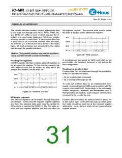
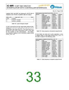
NL
NCS
NRD
Status
ST
ST
ST
ST
MT
MT
MT
LC
ERR
TMP
TMP
CRC
CRC
D(7:0)
Statusbit PDV
0x60
0x61
0x62
0x63
0x64
0x65
0x66
0x67
0x68
0x69
0x6A
0x6B
0x6C
0x6D
ADDR int
Wait for PDV=1
Read Data
PosData
Request
Figure 22: Position data output at request by pin NL
The status register data is output first. During the sta- out with each low signal at NRD.
tus register readout NRD should remain low until pin
D0 (in this case, PDV) switches to high, as this indi-
cates the validity of the position data.
The various ways of outputting position data in this
operating mode are set in register FULL_CYC. If bit
On each rising edge at NRD the internal address is FULL_CYC is set (Table 49), registers 0x60-0x6D are
increased, after which the position data can be read output on each cyclic access. If this bit is disabled,

 ICHAUS [ IC-HAUS GMBH ]