iC-MR 13-BIT S&H SIN/COS
INTERPOLATOR WITH CONTROLLER INTERFACES
Rev A1, Page 21/44
tion with the controlled sensor current source for LED is reached when the DC rate of the differential signals
supply (output ACO). The VDC potential automatically V(PSO)-V(NCO) and V(PCO)-V(NCO) is zero.
tracks higher photocurrents. In order to use this func-
tion intermediate potentials SVDC and CVDC have to
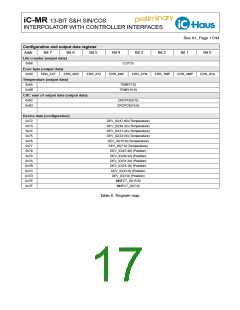
ORS
ORC
Code
0x0
Addr 0x08, bit 5:4
be adjusted to a minimal AC ripple using the selectable
k factor of parameters MPS and MPC (see Table 21).
If the gain setting is altered, this calibration has to be
repeated. When single-ended operating mode is se-
lected via register bit INMODE (see Table 12) MPS
and MPC have no impact and the applied voltage at
the negative input replaces the configurable sum volt-
age in the VDC generation.
Addr 0x0A, bit 5:4
Range
maxVOS = 3 * VOSREF
maxVOS = 6 * VOSREF
maxVOS = 18 * VOSREF
maxVOS = 36 * VOSREF
0x1
0x2
0x3
Note
The maximum offset calibration range refers to the
internal calibrated signals (calibration mode Analog
1, see page 18)
The feedback of pin voltage V(ACO) fulfills the same
task as source VDC when MR bridge sensors are sup-
plied by the controlled sensor current source. In this
case the justification of intermediate potentials MPS
and MPC is unnecessary.
Table 22: Offset calibration range sine, cosine
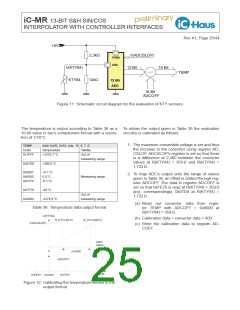
The principle interpolation accuracy of the sine/cosine
signals in dependancy with the selected calibration
range as well as the size of an LSB are exemplarily
illustrated for some values in the following table.
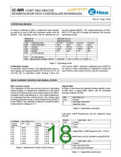
REFVOS
Code
Addr 0x0E, bit 5:4
Source type
0x0
Feedback of pin voltage V(ACO): V(ACO)/20
for supply-dependent diff. voltage signals
for Wheatstone measuring bridges
to measure VDDS
Range
x Source
maxVOS
Cal. step
size (LSB)
Limitation of
angle precision
@ 100 % (6 Vpp)
@ 50 % (3 Vpp)
0x1, 0x2
Fixed reference:
3 x 0.25 V
6 x 0.25 V
6 x 0.5 V
750 mV
1.5 V
3 V
733 µV
none (>13 bit)
none (>13 bit)
0x1 = V05 of 500 mV, 0x2 = V025 of 250 mV
for single-ended current or voltage signals
for single-ended or differential stabilized signals
(regulated sensors, frequency generator)
1466 µV
2933 µV
8798 µV
0.03°, >13 bit
0.06°, ca. 12 bit
0.06°, ca. 12.5 bit
0.11°, ca. 11.7 bit
0x3
Self-tracking sources VDC1, VDC2 (125...250 mV)
for differential current signals
for differential voltage signals*
18 x 0.5 V
9 V
0.17°, ca. 11 bit
0.34°, ca. 10 bit
Note
*) Requires SELREF = 0x3 and the supply of pin
VREF with the sensor’s reference potential (see
Elec. Char. No. 105 for acceptable input voltage).
Table 23: Offset calibration and impact on the angle
precision
Table 20: Offset reference source
OFS
OFC
Code
0x000
0x001
...
Addr 0x09, bit 7:0, Addr 0x0A, bit 2:0
Addr 0x0B, bit 7:0, Addr 0x0C, bit 2:0
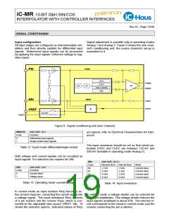
MPS
MPC
Code
0x000
0x001
...
Addr 0x06, bit 5:0, Addr 0x05, bit 7:4
Addr 0x08, bit 1:0, Addr 0x07, bit 7:0
VDC = k ∗ VPi + (1 − k) ∗ VNi
k = 0.33
Factor OF
Code
0x400
0x401
...
Factor OF
0
0
0.00098
−0.00098
−0.00098 ∗ OFx
−1
0.00098 ∗ OFx
1
k = 0.33032
0x3FF
0x7FF
...
k = 0.33 + Code · 0.00032
0x200
...
k = 0.50 (center setting)
Table 24: Offset calibration sine, cosine
...
0x3FF
Note
k = 0.66
Adjustment required only if VOSREF = 0x3
The calibrated offset is generated through
VOS() = maxVOS ∗ OF
Table 21: Intermediate potentials sine, cosine
Phase correction SIN vs. COS
The offset calibration range is dependent on the se- The phase shift between sine and cosine can be ad-
lected REFVOS source and is adjusted using registers justed using register value PH. If the phase error is
ORS and ORC. The actual offset calibration happens too high, some calibration parameters may have to be
through adjusting factors OFS and OFC after having adjusted again (those are amplitudes, intermediate po-
selected the calibration range. The calibration target tentials and offset voltages).

 ICHAUS [ IC-HAUS GMBH ]