iC-MR 13-BIT S&H SIN/COS
INTERPOLATOR WITH CONTROLLER INTERFACES
Rev A1, Page 23/44
AMPLITUDE CONTROL
iC-MR allows the amplitude of the output signals at Square control mode keeps the sum of the sine/cosine
pins PSO, NSO, PCO, and NCO to be kept constant amplitude squares at a constant value. Register ACOC
- regardless of temperature and ageing effects - by adjusts the setpoint for analog output ACO according
tracking the sensor supply. For this purpose iC-MR to Table 31.
has a controlled current source at pin ACO which can
ACOC
Code
0x00
Addr 0x00, bit 4:0
power the external sensor. The driver capability of this
current source is selected by ACOR (Table 27), the
control modes by ACOT (Table 28).
Square mode ACOT = 00
Vpp() ≈ 300 mV (60 %)
Vpp() ≈ 305 mV (61 %)
0x01
ACOR
Code
00
Addr 0x00, bit 6:5
Function
77
...
Vpp() ≈ 300 mV
77−(1.25∗Code)
5 mA - range
10 mA - range
25 mA - range
50 mA - range
0x19
...
Vpp() ≈ 500 mV (98 %)
...
01
10
0x1F
Vpp() ≈ 600 mV (120 %)
11
Table 31: AC Setpoint square control
Table 27: ACO Output current range (for control oper-
ation and constant current source)
~
Vpp() 500 mV
~
ACOT
Code
00
Addr 0x01, bit 0; Addr 0x00, bit 7
Function
~
Vpk() 250 mV
~
SIN/COS square control
Sum control
01
ϕ
10
Combined Sum and SIN/COS square control
Constant current source
As cos(ϕ)
11
Table 28: ACO Output control principle
LCMODE
Addr 0x02, bit 3
Function
Vt(max)
Vt(min)
Code
0
1
Optimized control
Standard control
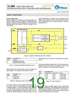
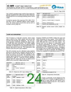
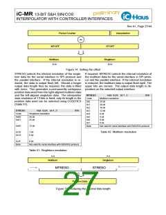
Figure 10: Signal monitoring with square control
(example: ACOC = 0x19; for Vt()min or
Vt()max; see Elec. Char. Nos. 809 and
810).
Table 29: Control mode
In sum control mode the sine and cosine DC values
(SVDC and CVDC) are added together and regulated
to the setpoint. The setpoint is configured using regis-
ter ACOD according to Table 30.
As opposed to square mode, sum mode gives a higher
accuracy. However, at higher signal frequencies it can-
not compensate for a reduction in the signal amplitude
caused by the amplifier cut-off frequency of the sen-
sors. The device thus has a combined control mode
which utilizes both control modes, sum and square
(see Table 28). In this mode sum control is applied at
low frequencies, with square control coming into play
at frequencies exceeding the cut-off frequency of the
sensor’s amplifiers. So that this control mode functions
correctly, the set signal amplitude for square control
mode must be lower than that for sum control.
ACOD
Code
0x00
Addr 0x01, bit 7:1
Sum mode ACOT = 01
VDC1 + VDC2 ≈ 166 mV
VDC1 + VDC2 ≈ 167 mV
0x01
109
...
VDC1 + VDC2 ≈ 166 mV
VDC1 + VDC2 ≈ 551 mV
109−(0.6∗Code)
0x7F
Table 30: DC Setpoint sum control

 ICHAUS [ IC-HAUS GMBH ]