iC-MR 13-BIT S&H SIN/COS
INTERPOLATOR WITH CONTROLLER INTERFACES
Rev A1, Page 19/44
SIGNAL CONDITIONING
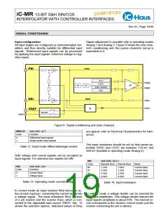
Input configuration
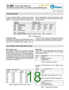
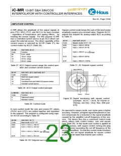
Signal adjustment is possible only in operating modes
All input stages are configured as instrumentation am- Analog 1 and Analog 2. Figure 8 shows the sine chan-
plifiers and thus directly suitable for differential input nel’s conditioning unit; the cosine channel’s set-up is
signals. Referenced input signals can be processed equivalent to it.
by applying the input signals’ reference voltage to neg-
ative inputs.
PSIN1
PSI
GFS
0.5 V
PSIN2
0.25 V
x
x
GR
OR
OF
0.05 x V(ACO)
VDC
NSIN2
NSIN1
NSI
GFS
VPAH
SVDC
k
VREF
SELREF
VREFI
Figure 8: Signal-conditioning unit (sine channel)
INMODE
Addr 0x0E, bit 7
are typical, refer to Electrical Characteristics for toler-
ances.
Code
Function
0
1
Differential input signals
Single-ended input signals
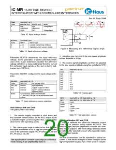
The input resistance should be set so that center po-
tentials SVDC and CVDC are between 125 mV and
250 mV (testable in operating mode Analog 2).
Table 12: Input mode differential/single-ended
Both voltage and current signals can be accepted as
input signals. For selection use register bit UIN.
RIN
Code
00
Addr 0x0E, bit 2:1
Nominal Rin() Internal Rui()
Mode
UIN
Code
0
Addr 0x0E, bit 0
Function
1.7 kΩ
2.5 kΩ
3.5 kΩ
4.9 kΩ
1.6 kΩ
2.3 kΩ
3.2 kΩ
4.6 kΩ
Current input
Current input
Current input
Current input
01
Current input
Voltage input
10
1
11
Table 13: Operating mode current/voltage
Table 14: Input resistance
In current mode an input restistor Rin() becomes ac-
tive at each input pin, converting the current signal into In voltage mode a voltage divider can be selected for
a voltage signal. The input resistance Rin() consists high input amplitudes. This voltage divider reduces the
of a pin resistor and the resistor Rui(), which is con- input signal’s amplitude to about 25%. The internal cir-
nected to the adjustable bias source VREFI. Tab. 14 cuit corresponds to the circuit in current mode, just the
shows the selection options. Indicated values of Rin() resistor connecting the pin is altered.

 ICHAUS [ IC-HAUS GMBH ]