HT95LXXX
Reset
V
D
D
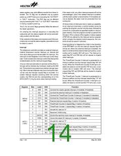
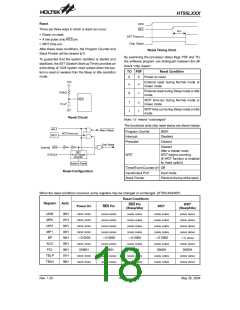
There are three ways in which a reset can occur.
R
E
S
t
S S T
·
·
·
Power on reset.
S
S
T
T
i
m
e
-
o
u
t
A low pulse onto RES pin.
WDT time-out.
C
h
i
p
R
e
s
e
t
After these reset conditions, the Program Counter and
Stack Pointer will be cleared to 0.
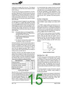
Reset Timing Chart
By examining the processor status flags PDF and TO,
the software program can distinguish between the dif-
ferent ²chip resets².
To guarantee that the system oscillator is started and
stabilized, the SST (System Start-up Timer) provides an
extra-delay of 1024 system clock pulses when the sys-
tem is reset or awakes from the Sleep or Idle operation
mode.
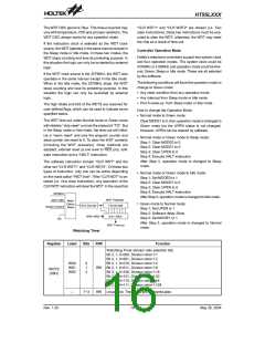
TO PDF
Reset Condition
Power on reset
0
u
0
u
V
D
D
External reset during Normal mode or
Green mode
External reset during Sleep mode or Idle
mode
1
0
0
k
0
1
1
1
u
1
R
E
S
WDT time-out during Normal mode or
Green mode
m
0 . 1 F
WDT time-out during Sleep mode or Idle
mode
Reset Circuit
Note: ²u² means ²unchanged²
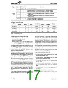
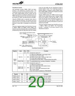
The functional units chip reset status are shown below:
H
A
L
T
W
a
r
m
R
e
s
e
t
Program Counter
Interrupt
000H
W
D
T
t
i
m
e
-
o
u
t
W
D
T
Disabled
Cleared
Prescaler
C
o
l
d
R
e
s
e
t
Cleared
E
x
t
e
r
n
a
l
R
E
S
After a master reset,
WDT begins counting.
(If WDT function is enabled
by mask option)
S
S
T
1
0
-
b
i
t
R
i
p
p
l
e
S
Y
S
C
L
K
WDT
C
o
u
n
t
e
r
S
y
s
t
e
m
R
e
s
e
t
Timer/Event Counter 0/1 Off
Reset Configuration
Input/output Port
Stack Pointer
Input mode
Points to the top of the stack
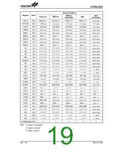
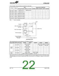
When the reset conditions occurred, some registers may be changed or unchanged. (HT95L400/40P)
Reset Conditions
Register
Addr.
RES Pin
(Sleep/Idle)
WDT
(Sleep/Idle)
Power On
RES Pin
WDT
IAR0
MP0
IAR1
MP1
BP
00H
01H
02H
03H
04H
05H
06H
07H
08H
xxxx xxxx
xxxx xxxx
xxxx xxxx
xxxx xxxx
---0 0000
xxxx xxxx
0000H
uuuu uuuu
uuuu uuuu
uuuu uuuu
uuuu uuuu
---0 0000
uuuu uuuu
0000H
uuuu uuuu
uuuu uuuu
uuuu uuuu
uuuu uuuu
---0 0000
uuuu uuuu
0000H
uuuu uuuu
uuuu uuuu
uuuu uuuu
uuuu uuuu
---0 0000
uuuu uuuu
0000H
uuuu uuuu
uuuu uuuu
uuuu uuuu
uuuu uuuu
---u uuuu
uuuu uuuu
0000H
ACC
PCL
TBLP
TBLH
xxxx xxxx
xxxx xxxx
uuuu uuuu
uuuu uuuu
uuuu uuuu
uuuu uuuu
uuuu uuuu
uuuu uuuu
uuuu uuuu
uuuu uuuu
Rev. 1.20
18
May 26, 2004

 HOLTEK [ HOLTEK SEMICONDUCTOR INC ]