HT95LXXX
routine call to location 0CH will occur. The interrupt
request flag T1F and EMI bits will be cleared to disable
further interrupts.
It is recommended that a program should not use the
²CALL subroutine² within the interrupt subroutine. Inter-
rupts often occur in an unpredictable manner or need to
be serviced immediately in some applications. If only
one stack is left and enabling the interrupt is not well
controlled, the original control sequence will be dam-
aged once the ²CALL² operates in the interrupt subrou-
tine.
The real time clock interrupt is generated by a 1Hz RTC
generator. When the RTC time-out occurs, the interrupt
request flag RTCF will be set. When the RTC interrupt is
enabled, the stack is not full and the RTCF is set, a sub-
routine call to location 14H will occur. The interrupt re-
quest flag RTCF and EMI bits will be cleared to disable
other interrupts.
Oscillator Configuration
There are two oscillator circuits in the controller, the ex-
ternal 32768Hz crystal oscillator and internal WDT
OSC.
The dialer I/O interrupt is triggered by any edge transi-
tion onto HKS pin or a falling edge transition onto HDI
pin or a rising edge transition onto HFI pin, the interrupt
request flag DRF will be set. When the dialer I/O inter-
rupt is enabled, the stack is not full and the DRF is set, a
subroutine call to location 18H will occur. The interrupt
request flag DRF and EMI bits will be cleared to disable
other interrupts.
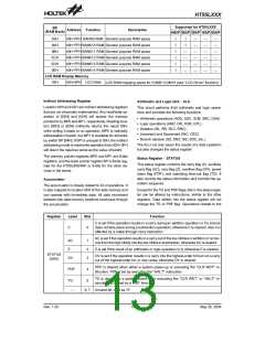
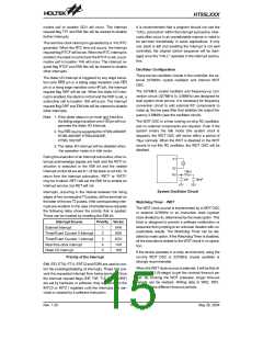
The 32768Hz crystal oscillator and frequency-up con-
version circuit (32768Hz to 3.58MHz) are designed for
dual system clock source. It is necessary for frequency
conversion circuit to add external RC components to
make up the low pass filter that stabilize the output fre-
quency 3.58MHz (see the oscillator circuit).
Note: 1. If the dialer status is on-hook and hold-line,
the falling edge transition onto HDI pin will not
generate the dialer I/O interrupt.
The WDT OSC is a free running on-chip RC oscillator,
and no external components are required. Even if the
system enters the Idle mode (the system clock is
stopped), the WDT OSC still works within a period of
78ms normally. When the WDT is disabled or the WDT
source is not this RC oscillator, the WDT OSC will be
disabled.
2. The HDI input is supported for HT95L400/40P,
HT95L300/30P, HT95L200/20P,
HT95L100/10P.
3. The dialer I/O interrupt will be disabled when
the operation mode is in Idle mode.
During the execution of an interrupt subroutine, other in-
terrupt acknowledge signals are held until the RETI in-
struction is executed or the EMI bit and the related
interrupt control bit are set to 1 (if the stack is not full). To
return from the interrupt subroutine, ²RET² or ²RETI²
may be invoked. RETI will set the EMI bit to enable an
interrupt service, but RET will not.
X
1
X
2
1
5
k
X
C
3
n
F
5
0
n
F
System Oscillator Circuit
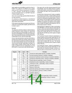
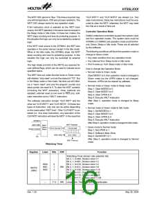
Interrupts, occurring in the interval between the rising
edges of two consecutive T2 pulses, will be serviced on
the latter of the two T2 pulses, if the corresponding inter-
rupts are enabled. In the case of simultaneous requests
the following table shows the priority that is applied.
These can be masked by resetting the EMI bit.
Watchdog Timer - WDT
The WDT clock source is implemented by a WDT OSC
or external 32768Hz or an instruction clock (system
clock divided by 4), determined by the mask option. This
timer is designed to prevent a software malfunction or
sequence from jumping to an unknown location with un-
predictable results. The Watchdog Timer can be dis-
abled by mask option. If the Watchdog Timer is disabled,
all the executions related to the WDT result in no opera-
tion.
Interrupt Source
External interrupt
Priority Vector
1
2
3
4
5
04H
08H
0CH
14H
18H
Timer/Event Counter 0 interrupt
Timer/Event Counter 1 interrupt
Real time clock interrupt
Dialer I/O interrupt
If the device operates in a noisy environment, using the
on-chip WDT OSC or 32768Hz crystal oscillator is
strongly recommended.
Priority of the Interrupt
EMI, EEI, ET0I, ET1I, ERTCI and EDRI are used to con-
trol the enabling/disabling of interrupts. These bits pre-
vent the requested interrupt from being serviced. Once
the interrupt request flags (EIF, T0F, T1F, RTCF, DRF)
are set by hardware or software, they will remain in the
INTC0 or INTC1 registers until the interrupts are ser-
viced or cleared by a software instruction.
When the WDT clock source is selected, it will be first di-
vided by 512 (9-stage) to get the nominal time-out pe-
riod. By invoking the WDT prescaler, longer time-out
periods can be realized. Writing data to WS2, WS1,
WS0 can give different time-out periods.
Rev. 1.20
15
May 26, 2004

 HOLTEK [ HOLTEK SEMICONDUCTOR INC ]