HT95LXXX
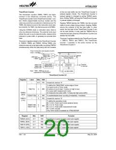
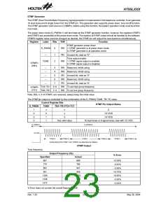
The TMR0C is the Timer/Event Counter 0 control regis-
ter, which defines the Timer/Event Counter 0 options.
The Timer/Event Counter 1 has the same options as the
Timer/Event Counter 0 and is defined by TMR1C. The
timer/event counter control registers define the operat-
ing mode, counting enable or disable and active edge.
In the case of timer/event counter off condition, writing
data to the timer/event counter preload register also re-
loads that data to the timer/event counter. But if the
timer/event counter is turned on, data written to the
timer/event counter is reserved only in the timer/event
counter preload register. The timer/event counter will go
on operating until an overflow occurs.
The T0M0/T1M0, T0M1/T1M1 bits define the operating
mode. The event count mode is used to count external
events, which means the clock source comes from an
external (TMR0 or INT/TMR1) pin. The timer mode func-
tions as a normal timer with the clock source coming
from instruction clock (TMR0) or 32768Hz (TMR1). The
pulse width measurement mode can be used to count
the high or low level duration of the external signal
(TMR0 or INT/TMR1). The counting is based on the
32768Hz clock for TMR1 or instruction clock for TMR0.
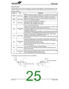
Input/Output Ports
There is a maximum of 40 bidirectional input/output
lines in the HT95LXXX family MCU, labeled as PA, PB,
PD, PE, PF and PG. All of these I/O ports can be used
for input and output operations. For input operation,
these ports are non-latching, that is, the inputs must be
ready at the T2 rising edge of instruction “MOV A,[m]”
(m=12H, 14H, 18H, 1AH, 34H or 36H). For output oper-
ation, all the data is latched and remains unchanged un-
til the output latch is rewritten.
In the event count or timer mode, once the timer/event
counter starts counting, it will count from the current
contents in the timer/event counter to FFFFH. If an over-
flow occurs, the counter is reloaded from the timer/event
counter preload register and generates the correspond-
ing interrupt request flag (T0F/T1F) at the same time.
Note that the event count mode is not available for
HT95L000/00P.
Each I/O line has its own control register (PAC, PBC,
PDC, PEC, PFC, PGC) to control the input/output con-
figuration. With this control register, CMOS output or
Schmitt trigger input can be reconfigured dynamically
under software control. To make one I/O line to function
as an input line, the corresponding latch of the control
register must be written with a ²1². The pull-high resis-
tance shows itself automatically if the pull-high option is
selected. The input source also depends on the control
register. If the control register bit is ²1², the input will
read the pad state. If the control register bit is ²0², the
contents of the latches will move to the internal bus. The
latter is possible in the ²read-modify-write² instruction.
For output function, CMOS is the only configuration.
Each bit of these input/output latches can be set or
cleared by ²SET [m].i² and ²CLR [m].i² (m=12H, 14H,
18H, 1AH, 34H or 36H) instructions.
In pulse width measurement mode with the
T0ON/T1ON and T0E/T1E bits equal to 1, once the
TMR0/TMR1 pin has received a transient from low to
high (or high to low; if the T0E/T1E bit is 0) it will start
counting until the TMR0/TMR1 pin returns to the original
level and resets the T0ON/T1ON. The measured result
will remain in the timer/event counter even if the acti-
vated transient occurs again. In other words, only 1 cy-
cle measurement can be done. Until setting the
T0ON/T1ON, the cycle measurement will function again
as long as it receives further transient pulse. Note that,
in this operating mode, the timer/event counter starts
counting not according to the logic level but according to
the transient edges. In the case of counter overflows,
the counter is reloaded from the timer/event counter
preload register and continue to measure the width and
issues the interrupt request just like the other two
modes. Note that this mode is not available for
HT95L000/00P.
Some instructions first input data and then follow the
output operations. For example, ²SET [m].i², ²CLR
[m].i², ²CPL [m]², ²CPLA [m]² read the entire port states
into the CPU, execute the defined operations
(bit-operation), and then write the results back to the
latches or the accumulator.
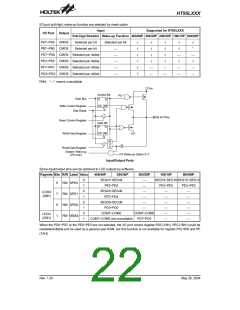
Each line of port A has the capability of waking-up the
device. They are selected by mask option per bit.
To enable the counting operation, the timer on bit
(T0ON/T1ON) should be set to 1. In the pulse width
measurement mode, the T0ON/T1ON will be cleared
automatically after the measurement cycle is com-
pleted. But in the other two modes the T0ON/T1ON can
only be reset by instruction. The overflow of the
timer/event counter is one of the wake-up sources. No
matter what the operation mode is, writing a 0 to
ET0I/ET1I can disable the corresponding interrupt ser-
vice.
There is a pull-high option available for all I/O lines.
Once the pull-high option of an I/O line is selected, the
I/O lines have pull-high resistor. Otherwise, the pull-high
resistor is absent. It should be noted that a non-pull-high
I/O line operating in input mode may cause a floating
state.
Rev. 1.20
21
May 26, 2004

 HOLTEK [ HOLTEK SEMICONDUCTOR INC ]