HT95LXXX
status register may yield different results from those in-
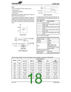
tended. The TO flag can be affected only by system
power-up, a WDT time-out or executing the ²CLR WDT²
or ²HALT² instruction. The PDF flag can be affected
only by executing the ²HALT² or ²CLR WDT² instruction
or during a system power-up.
If the stack is full, any other interrupt request will not be
acknowledged, even if the related interrupt is enabled,
until the stack pointer is decremented. If immediate ser-
vice is desired, the stack must be prevented from be-
coming full.
All these kinds of interrupts have a wake-up capability.
As an interrupt is serviced, a control transfer occurs by
pushing the program counter onto the stack, followed by
a branch to a subroutine at specified location in the pro-
gram memory. Only the program counter is pushed onto
the stack. If the contents of the register or status register
(STATUS) are altered by the interrupt service program
which corrupts the desired control sequence, the con-
tents should be saved in advance.
The Z, OV, AC and C flags generally reflect the status of
the latest operations.
On entering the interrupt sequence or executing the
subroutine call, the status register will not be automati-
cally pushed onto the stack.
If the contents of the status are important and if the sub-
routine can corrupt the status register, precautions must
be taken to save it .
External interrupt is triggered by a high to low transition
of the INT/TMR1 pin and the interrupt request flag EIF
will be set. When the external interrupt is enabled, the
stack is not full and the external interrupt is active, a sub-
routine call to location 04H will occur. The interrupt re-
quest flag EIF and EMI bits will be cleared to disable
other interrupts.
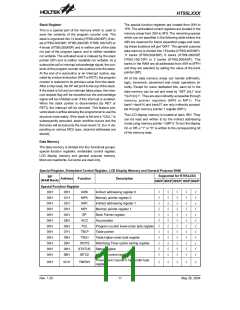
Interrupt
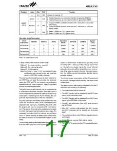
The telephone controller provides an external interrupt,
internal timer/event counter interrupt, an internal real
time clock interrupt and internal dialer I/O interrupt. The
Interrupt Control Registers 0 and Interrupt Control Reg-
ister 1 both contains the interrupt control bits that set the
enable/disable and the interrupt request flags.
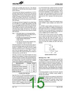
The Timer/Event Counter 0 interrupt is generated by a
timeout overflow and the interrupt request flag T0F will
be set. When the Timer/Event Counter 0 interrupt is en-
abled, the stack is not full and the T0F bit is set, a sub-
routine call to location 08H will occur. The interrupt
request flag T0F and EMI bits will be cleared to disable
further interrupts.
Once an interrupt subroutine is serviced, all the other in-
terrupts will be blocked (by hardware clearing the EMI
bit). This scheme may prevent any further interrupt nest-
ing. Other interrupt requests may occur during this inter-
val but only the interrupt request flag is recorded. If a
certain interrupt requires servicing within the service
routine, the EMI bit and the corresponding bit of the
INTC0 (INTC1) may be set to allow interrupt nesting.
The Timer/Event Counter 1 interrupt is generated by a
timeout overflow and the interrupt request flag T1F will
be set. When the Timer/Event Counter 1 interrupt is en-
abled, the stack is not full and the T1F bit is set, a sub-
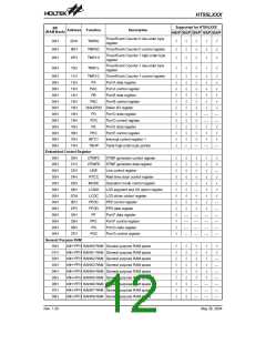
Register
Bits
0
Label
EMI
EEI
R/W
RW
RW
RW
RW
RW
RW
RW
RO
Function
Controls the master (global) interrupt (1=enabled; 0=disabled)
Controls the external interrupt (1=enabled; 0=disabled)
Controls the Timer/Event Counter 0 interrupt (1=enabled; 0=disabled)
Controls the Timer/Event Counter 1 interrupt (1=enabled; 0=disabled)
External interrupt request flag (1=active; 0=inactive)
Timer/Event Counter 0 request flag (1=active; 0=inactive)
Timer/Event Counter 1 request flag (1=active; 0=inactive)
Unused bit, read as ²0²
1
2
ET0I
ET1I
EIF
3
INTC0
(0BH)
4
5
T0F
T1F
¾
6
7
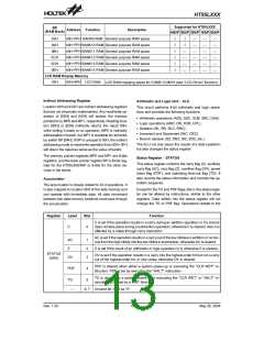
0
RW
RW
RW
RO
Reserved, inhibit using
¾
1
ERTCI
EDRI
¾
Control the real time clock interrupt (1=enable; 0=disable)
Control the dialer I/O interrupt (1=enable; 0=disable)
Unused bit, read as ²0²
2
3
INTC1
(1EH)
4
RW
RW
RW
RO
Reserved, inhibit using
¾
5
RTCF
DRF
¾
Internal real time clock interrupt request flag (1=active; 0=inactive)
Internal dialer I/O interrupt request flag (1=active: 0=inactive)
Unused bit, read as ²0²
6
7
Rev. 1.20
14
May 26, 2004

 HOLTEK [ HOLTEK SEMICONDUCTOR INC ]