HT95LXXX
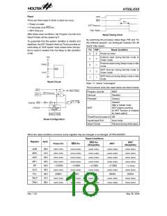
The WDT OSC period is 78ms. This time-out period may
vary with temperature, VDD and process variations. The
WDT OSC always works for any operation mode.
²CLR WDT1² and ²CLR WDT2² are chosen (i.e. Two
clear instructions), these two instructions must be exe-
cuted to clear the WDT; otherwise, the WDT may reset
the chip as a result of time-out.
If the instruction clock is selected as the WDT clock
source, the WDT operates in the same manner except in
the Sleep mode or Idle mode. In these two modes, the
WDT stops counting and lose its protecting purpose. In
this situation the logic can only be re-started by external
logic.
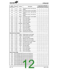
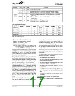
Controller Operation Mode
Holtek¢s telephone controllers support two system clock
and four operation modes. The system clock could be
32768Hz or 3.58MHz and operation mode could be Nor-
mal, Green, Sleep or Idle mode. These are all selected
by the software.
If the WDT clock source is the 32768Hz, the WDT also
operates in the same manner except in the Idle mode.
When in the Idle mode, the 32768Hz stops, the WDT
stops counting and lose its protecting purpose. In this
situation the logic can only be re-started by external
logic.
The following conditions will force the operation mode to
change to Green mode:
·
·
·
Any reset condition from any operation mode
Any interrupt from Sleep mode or Idle mode
Port A wake-up from Sleep mode or Idle mode
The high nibble and bit3 of the WDTS are reserved for
user defined flags, which can be used to indicate some
specified status.
How to change the Operation Mode
·
Normal mode to Green mode:
The WDT time-out under Normal mode or Green mode
will initialize ²chip reset² and set the status bit ²TO². But
in the Sleep mode or Idle mode, the time-out will initial-
ize a ²warm reset² and only the program counter and
stack pointer are reset to 0. To clear the WDT contents
(including the WDT prescaler), three methods are
adopted; external reset (a low level to RES pin), soft-
ware instruction and a ²HALT² instruction.
Clear MODE1 to 0, then operation mode is changed to
Green mode but the UPEN status is not changed.
However, UPEN can be cleared by software.
·
Normal mode or Green mode to Sleep mode:
Step 1: Clear MODE0 to 0
Step 2: Clear MODE1 to 0
Step 3: Clear UPEN to 0
Step 4: Execute HALT instruction
After Step 4, operation mode is changed to Sleep
mode.
The software instruction include ²CLR WDT² and the
other set ²CLR WDT1² and ²CLR WDT2². Of these two
types of instruction, only one can be active depending
on the mask option ²WDT instr². If the ²CLR WDT² is se-
lected (i.e. One clear instruction), any execution of the
CLR WDT instruction will clear the WDT. In the case that
·
·
Normal mode or Green mode to Idle mode:
Step 1: Set MODE0 to 1
Step 2: Clear MODE1 to 0
Step 3: Clear UPEN to 0
Step 4: Execute HALT instruction
After Step 4, operation mode is changed to Idle mode.
3
2
7
6
8
H
z
W
D
T
O
S
C
W
D
T
P
r
e
s
c
a
l
e
r
M
a
s
k
Green mode to Normal mode:
Step 1: Set UPEN to 1
O
p
t
i
o
n
9
-
b
i
t
C
o
u
n
t
e
r
7
-
b
i
t
C
o
u
n
t
e
r
S
y
s
t
e
m
C
l
o
c
k
/
4
S
e
l
e
c
t
Step 2: Software delay 20ms
Step 3: Set MODE1 to 1
8
-
t
o
-
1
M
U
X
W
S
0
~
W
S
2
After Step 3, operation mode is changed to Normal
mode.
W
D
T
T
i
m
e
-
o
u
t
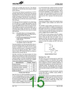
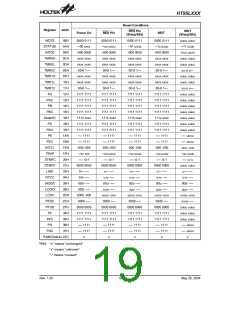
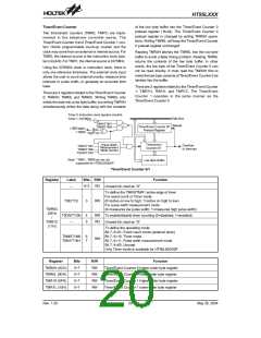
Watchdog Timer
Register
Label
Bits
R/W
Function
Watchdog Timer division ratio selection bits
Bit 2, 1, 0=000, Division ratio=1:1
Bit 2, 1, 0=001, Division ratio=1:2
Bit 2, 1, 0=010, Division ratio=1:4
WS0
WS1
WS2
0
1
2
RW Bit 2, 1, 0=011, Division ratio=1:8
Bit 2, 1, 0=100, Division ratio=1:16
Bit 2, 1, 0=101, Division ratio=1:32
Bit 2, 1, 0=110, Division ratio=1:64
Bit 2, 1, 0=111, Division ratio=1:128
WDTS
(09H)
7~3
RW Unused bit. These bits are read/write-able.
¾
Rev. 1.20
16
May 26, 2004

 HOLTEK [ HOLTEK SEMICONDUCTOR INC ]