HT95LXXX
Timer/Event Counter
of the low byte buffer into the Timer/Event Counter 0
preload register (16-bit). The Timer/Event Counter 0
preload register is changed by writing TMR0H opera-
tions. Writing TMR0L will keep the Timer/Event Counter
0 preload register unchanged.
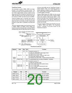
Two timer/event counters (TMR0, TMR1) are imple-
mented in the telephone controller series. The
Timer/Event Counter 0 and Timer/Event Counter 1 con-
tain 16-bits programmable count-up counter and the
clock may come from an external or internal source. For
TMR0, the internal source is the instruction clock (sys-
tem clock/4). For TMR1, the internal source is 32768Hz.
Reading TMR0H latches the TMR0L into the low byte
buffer to avoid a false timing problem. Reading TMR0L
returns the contents of the low byte buffer. In other
words, the low byte of the Timer/Event Counter 0 can
not be read directly. It must read the TMR0H first to
make the low byte contents of Timer/Event Counter 0 be
latched into the buffer.
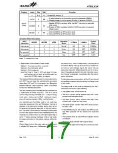
Using the 32768Hz clock or instruction clock, there is
only one reference time-base. The external clock input
allows the user to count external events, measure time
intervals or pulse width, or generate an accurate time
base.
There are 3 registers related to the Timer/Event Counter
1; TMR1H, TMR1L and TMR1C. The Timer/Event
Counter 1 operates in the same manner as the
Timer/Event Counter 0.
There are 3 registers related to the Timer/Event Counter
0; TMR0H, TMR0L and TMR0C. Writing TMR0L only
writes the data into a low byte buffer, but writing TMR0H
simultaneously writes the data along with the contents
T
i
m
e
r
0
:
I
n
s
t
r
u
c
t
i
o
n
c
l
o
c
k
(
s
y
s
t
e
m
c
l
o
c
k
/
4
)
D
a
t
a
B
u
s
T
i
m
e
r
1
:
3
2
7
6
8
H
z
T
0
M
1
/
T
1
M
1
R
e
l
o
a
d
T
i
m
e
r
/
E
v
e
n
t
C
o
u
n
t
e
r
0
/
1
T
0
M
0
/
T
1
M
0
I
N
T
/
T
M
R
1
*
P
r
e
l
o
a
d
R
e
g
i
s
t
e
r
T
M
R
0
*
T
0
E
/
T
1
E
T
i
m
e
r
/
e
v
e
n
t
P
u
l
s
e
W
i
d
t
h
O
v
e
r
f
l
o
w
T
T
0
M
1
/
/
T
T
1
M
1
M
e
a
s
u
r
e
m
e
n
t
C
o
u
n
t
e
r
0
/
1
t
o
I
n
t
e
r
r
u
p
t
0
M
0
1
M
0
M
o
d
e
C
o
n
t
r
o
l
T
0
O
N
/
T
1
T
O
N
N
o
t
e
:
*
T
M
R
1
,
M
R
0
p
i
n
a
r
e
n
o
t
L
o
w
B
y
t
e
B
u
f
f
e
r
s
u
p
p
o
r
t
e
d
f
o
r
H
T
9
5
L
0
0
0
/
0
0
P
.
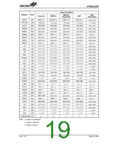
Timer/Event Counter 0/1
Register
Label
Bits R/W
Function
0~2
RO
¾
Unused bit, read as ²0²
To define the TMR0/TMR1 active edge of timer
For event count or Timer mode
T0E/T1E
3
RW (0=active on low to high; 1=active on high to low)
For pulse width measurement mode
TMR0C
(0EH)
/
(0=measures low pulse width; 1=measures high pulse width)
T0ON/T1ON
4
5
RW To enable/disable timer counting (0=disabled; 1=enabled)
RO
TMR1C
(11H)
¾
Unused bit, read as ²0²
To define the operating mode
Bit 7, 6=01, Event count mode (external clock)
Bit 7, 6=10, Timer mode
T0M0/T1M0
T0M1/T1M1
6
7
RW
Bit 7, 6=11, Pulse width measurement mode
Bit 7, 6=00, Unused
Only Timer mode is available for HT95L000/00P.
Register
Bits
0~7
0~7
0~7
0~7
R/W
Function
TMR0H (0CH)
TMR0L (0DH)
TMR1H (0FH)
TMR1L (10H)
RW
RW
RW
RW
Timer/Event Counter 0 higher-order byte register
Timer/Event Counter 0 lower-order byte register
Timer/Event Counter 1 higher-order byte register
Timer/Event Counter 1 lower-order byte register
Rev. 1.20
20
May 26, 2004

 HOLTEK [ HOLTEK SEMICONDUCTOR INC ]