HT95LXXX
Supported for HT95LXXX
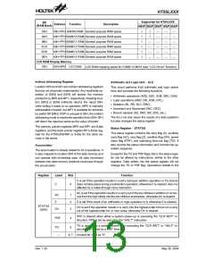
BP
(RAM Bank)
Address
Function
Description
400/P 300/P 200/P 100/P 000/P
09H
0AH
0BH
0CH
0DH
0EH
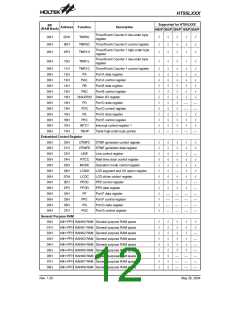
40H~FFH BANK9 RAM General purpose RAM space
40H~FFH BANK10 RAM General purpose RAM space
40H~FFH BANK11 RAM General purpose RAM space
40H~FFH BANK12 RAM General purpose RAM space
40H~FFH BANK13 RAM General purpose RAM space
40H~FFH BANK14 RAM General purpose RAM space
Ö
Ö
Ö
Ö
Ö
Ö
Ö
¾
¾
¾
¾
¾
¾
¾
¾
¾
¾
¾
¾
¾
¾
¾
¾
¾
¾
Ö
¾
¾
¾
¾
LCD RAM Display Memory
1BH
40H~9FH LCD RAM
LCD RAM mapping space for COM0~COM15 (see ²LCD Driver² function)
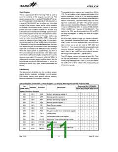
Indirect Addressing Register
Arithmetic and Logic Unit - ALU
Location 00H and 02H are indirect addressing registers
that are not physically implemented. Any read/write op-
eration of [00H] and [02H] will access the memory
pointed to by MP0 and MP1, respectively. Reading loca-
tion [00H] or [02H] indirectly returns the result 00H,
while writing it leads to no operation. MP0 is indirectly
addressable in bank0, but MP1 is available for all banks
by switch BP [04H]. If BP is unequal to 00H, the indirect
addressing mode to read/write operation from 00H~3FH
will return the result as same as the value of bank0.
This circuit performs 8-bit arithmetic and logic opera-
tions and provides the following functions:
·
·
·
·
·
Arithmetic operations (ADD, ADC, SUB, SBC, DAA)
Logic operations (AND, OR, XOR, CPL)
Rotation (RL, RR, RLC, RRC)
Increment and Decrement (INC, DEC)
Branch decision (SZ, SNZ, SIZ, SDZ, etc.)
The ALU not only saves the results of a data operation
but also changes the status register.
The memory pointer registers MP0 and MP1 are 8-bits
registers, and the bank pointer register BP is 6-bits reg-
ister for the HT95L400/40P or 5-bits for the other de-
vices in the series.
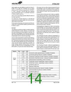
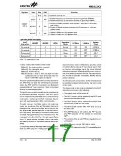
Status Register - STATUS
This status register contains the carry flag (C), auxiliary
carry flag (AC), zero flag (Z), overflow flag (OV), power
down flag (PDF), and watchdog time-out flag (TO). It
also records the status information and controls the op-
eration sequence.
Accumulator
The accumulator is closely related to ALU operations. It
is also mapped to location 05H of the data memory and
can operate with immediate data. All data movement
between two data memory locations must pass through
the accumulator.
Except for the TO and PDF flags, bits in the status regis-
ter can be altered by instructions, similar to the other
registers. Data written into the status register will not
change the TO or PDF flag. Operations related to the
Register
Label
Bits
Function
C is set if the operation results in a carry during an addition operation or if a borrow
does not take place during a subtraction operation; otherwise C is cleared. Also it is
affected by a rotate through carry instruction.
C
0
AC is set if the operation results in a carry out of the low nibbles in addition or no bor-
row from the high nibble into the low nibble in subtraction; otherwise AC is cleared.
AC
Z
1
2
3
Z is set if the result of an arithmetic or logic operation is 0; otherwise Z is cleared.
STATUS
(0AH)
OV is set if the operation results in a carry into the highest-order bit but not a carry
out of the highest-order bit, or vice versa; otherwise OV is cleared.
OV
PDF is cleared when either a system power-up or executing the ²CLR WDT² in-
struction. PDF is set by executing the ²HALT² instruction.
PDF
4
TO is cleared by a system power-up or executing the ²CLR WDT² or ²HALT² in-
struction. TO is set by a WDT time-out.
TO
5
6, 7
¾
Unused bit, read as ²0²
Rev. 1.20
13
May 26, 2004

 HOLTEK [ HOLTEK SEMICONDUCTOR INC ]