HT95LXXX
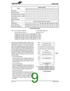
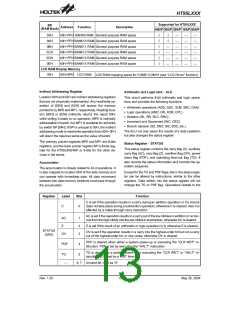
Program Counter
Mode
*13 *12 *11 *10 *9
*8
0
0
0
0
0
0
*7
0
0
0
0
0
0
*6
0
0
0
0
0
0
*5
0
0
0
0
0
0
*4
0
0
0
0
1
1
*3
0
0
1
1
0
1
*2
0
1
0
1
1
0
*1
0
0
0
0
0
0
*0
0
0
0
0
0
0
Initial reset
0
0
0
0
0
0
0
0
0
0
0
0
0
0
0
0
0
0
0
0
0
0
0
0
0
0
0
0
0
0
External interrupt
Timer/Event Counter 0 overflow
Timer/Event Counter 1 overflow
RTC interrupt
Dialer I/O interrupt
Skip
Program Counter+2 (within current bank)
*13 *12 *11 *10 *9 *8 @7 @6 @5 @4 @3 @2 @1 @0
Loading PCL
Jump, call branch
Return from subroutine
BP.5 #12 #11 #10 #9 #8 #7 #6 #5 #4 #3 #2 #1 #0
S13 S12 S11 S10 S9 S8 S7 S6 S5 S4 S3 S2 S1 S0
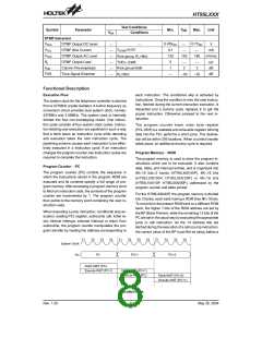
Program ROM Address
Note: *13~*0: Program counter bits
S13~S0: Stack register bits
#12~#0: Instruction code bits
@7~@0: PCL bits
Available bits of program counter for HT95L400/40P: Bit 13~Bit 0
Available bits of program counter for HT95L300/30P: Bit 12~Bit 0
Available bits of program counter for HT95L200/20P: Bit 12~Bit 0
Available bits of program counter for HT95L100/10P: Bit 11~Bit 0
Available bits of program counter for HT95L000/00P: Bit 11~Bit 0
jump or call is executed. When either a software or hard-
0
0
0
0
0
0
0
4
8
H
H
H
D
e
v
i
c
e
I
n
i
t
i
a
l
i
z
a
t
i
o
n
P
r
o
g
r
a
m
ware interrupt is received, note that no matter which
ROM bank the program is in, the program will always
jump to the appropriate interrupt service address in
Bank 0. The original 14 bits address will be stored on the
stack and restored when the relevant RET/RETI instruc-
tion is executed, automatically returning the program to
the original ROM bank. This eliminates the need for pro-
grammers to manage the BP when interrupts occur.
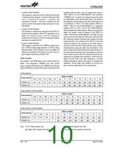
Certain locations in the program memory are reserved
for special usage:
E
x
t
e
r
n
a
l
I
n
t
e
r
r
u
p
t
S
u
b
r
o
u
t
i
n
e
T
i
m
e
r
/
E
v
e
n
t
C
o
u
n
t
e
r
0
I
n
t
e
r
r
u
p
t
S
u
b
r
o
u
t
i
n
e
0
0
C
H
T
i
m
e
r
/
E
v
e
n
t
C
o
u
n
t
e
r
1
I
n
t
e
r
r
u
p
t
S
u
b
r
o
u
t
i
n
e
0
1
0
H
R
e
s
e
r
v
e
d
0
0
1
1
4
8
H
H
R
T
C
I
n
t
e
r
r
u
p
t
S
u
b
r
o
u
t
i
n
e
P
r
o
g
r
a
m
R
O
M
D
i
a
l
e
r
I
/
O
I
n
t
e
r
r
u
p
t
S
u
b
r
o
u
t
i
n
e
·
Location 0000H (Bank0)
1
0
0
H
L
o
o
k
-
u
p
T
a
b
l
e
(
2
5
6
W
o
r
d
s
)
This area is reserved for the initialization program. Af-
ter chip power-on reset or external reset or WDT
time-out reset, the program always begins execution
at location 0000H.
1
F
F
H
L
o
o
k
-
u
p
T
a
b
l
e
(
2
5
6
W
o
r
d
s
)
·
·
Location 0004H (Bank0)
(
L
a
s
t
P
a
g
e
s
)
This area is reserved for the external interrupt service
program. If the INT/TMR1 input pin is activated, the
external interrupt is enabled and the stack is not full,
the program begins execution at location 0004H.
1
6
b
i
t
s
N
o
t
e
:
T
h
e
L
a
s
t
p
a
g
e
f
o
r
H
T
9
5
L
4
0
0
/
4
0
P
i
s
3
F
0
0
H
~
3
F
F
F
H
T
T
T
T
h
h
h
h
e
e
e
e
L
L
L
L
a
a
a
a
s
s
s
s
t
t
t
t
p
p
p
p
a
a
a
a
g
g
g
g
e
e
e
f
f
f
f
o
o
o
r
r
r
H
H
H
H
T
T
T
T
9
9
9
9
5
5
5
5
L
L
L
L
3
2
1
0
0
0
0
0
0
0
0
/
/
/
/
3
2
1
0
0
0
0
0
P
P
P
P
i
i
i
i
s
s
s
s
1
1
0
0
F
F
F
F
0
0
0
0
0
0
0
0
H
H
H
H
~
~
~
~
1
1
0
0
F
F
F
F
F
F
F
F
F
F
F
F
H
H
H
H
e
o
r
0
Location 0008H (Bank0)
Program Memory
This area is reserved for the Timer/Event Counter 0 in-
terrupt service program. If a timer interrupt results
from a Timer/Event Counter 0 overflow, the
Timer/Event Counter 0 interrupt is enabled and the
stack is not full, the program begins execution at loca-
tion 0008H.
Rev. 1.20
9
May 26, 2004

 HOLTEK [ HOLTEK SEMICONDUCTOR INC ]