HT46RU66/HT46CU66
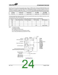
The overflow of the Timer/Event Counter 0/1/2 is one of
the wake-up sources. The Timer/Event Counter 0/1 can
also be applied to a PFD or Programmable Frequency
Divider whose output is on pin PA3 via a configuration
option. Only one PFD (PFD0 or PFD1) can be applied to
PA3 by options. No matter what the operation mode is,
writing a ²0² to ET0I, ET1I or ET2I disables the related
interrupt service. When the PFD function is selected, ex-
ecuting the ²SET [PA].3² instruction will enable the PFD
output and executing the ²CLR [PA].3² instruction will
disable the PFD output.
timer control register. Note that setting the timer enable
bit high to turn the timer on, should only be executed af-
ter the timer mode bits have been properly setup. Set-
ting the timer enable bit high together with a mode bit
modification, may lead to improper timer operation if ex-
ecuted as a single timer control register byte write in-
struction.
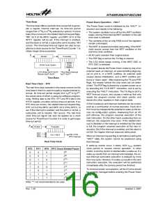
When the timer/event counter is read, the clock is
blocked to avoid errors. As this may results in a counting
error, blocking of the clock should be taken into account
by the programmer.
If the timer/event counter is not running, writing data to
the timer/event counter preload register will also reload
that data to the timer/event counter. But if the
timer/event counter running, data written to the
timer/event counter is kept only in the timer/event coun-
ter preload register. The timer/event counter continues
to operate until an overflow occurs at which point the
new data will be loaded from the preload register into the
timer/event counter.
It is strongly recommended to load a desired value into
the TMR0/TMR1/TMR2 registers first, before turning on
the related timer/event counter, for proper operation
since the initial value of the TMR0/TMR1/TMR2 regis-
ters are unknown. Due to the timer/event counter
scheme, the programmer should pay special attention
to the instruction to enable then disable the timer for the
first time, whenever there is a need to use the
timer/event counter function, to avoid unpredictable re-
sult. After this procedure, the timer/event counter func-
tion can be operated normally.
After the timer has been initialised the timer can be
turned on and off by controlling the enable bit in the
P
W
M
(
6
+
2
)
o
r
(
7
+
1
)
T
o
P
D
0
/
P
D
1
/
P
D
2
/
P
D
3
C
i
r
c
u
i
t
C
o
m
p
a
r
e
D
a
t
a
B
u
s
f
S Y S
8
-
s
t
a
g
e
P
r
e
s
c
a
l
e
r
L
o
w
B
y
t
e
f
I
N
T
B
u
f
f
e
r
8
-
1
M
U
X
T
0
M
1
T
0
M
0
T
0
P
S
C
2
~
T
0
P
S
C
0
T
M
R
0
1
6
-
B
i
t
R
e
l
o
a
d
P
r
e
l
o
a
d
R
e
g
i
s
t
e
r
T
0
E
P
u
l
s
e
W
i
d
t
h
O
v
e
r
f
l
o
w
t
o
I
n
t
e
r
r
u
p
t
H
i
g
h
B
y
t
e
L
o
w
B
y
t
e
T
0
M
1
M
e
a
s
u
r
e
m
e
n
t
T
0
M
0
M
o
d
e
C
o
n
t
r
o
l
1
6
-
B
i
t
T
i
m
e
r
/
E
v
e
n
t
C
o
u
n
t
e
r
T
0
O
N
P
F
D
0
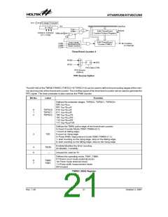
Timer/Event Counter 0
D
a
t
a
B
u
s
L
o
w
B
y
t
e
f
I N T
S
Y
S
B
u
f
f
e
r
M
U
X
3
2
7
6
8
H
z
T
1
M
1
T
1
S
T
1
M
0
T
M
R
1
1
6
-
B
i
t
R
e
l
o
a
d
P
r
e
l
o
a
d
R
e
g
i
s
t
e
r
T
1
E
P
u
l
s
e
W
i
n
d
t
h
T
1
M
1
O
v
e
r
f
l
o
w
t
o
I
n
t
e
r
r
u
p
t
H
i
g
h
B
y
t
e
L
o
w
B
y
t
e
M
e
a
s
u
r
e
m
e
n
t
T
1
M
0
M
o
d
e
C
o
t
r
o
l
T
1
O
N
1
6
-
B
i
t
T
i
m
e
r
/
E
v
e
n
t
C
o
u
n
t
e
r
P
F
D
1
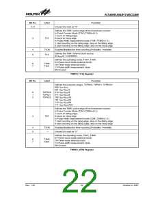
Timer/Event Counter 1
Rev. 1.20
20
October 2, 2007

 HOLTEK [ HOLTEK SEMICONDUCTOR INC ]