HT46RU66/HT46CU66
f
S Y S
8
-
s
t
a
g
e
P
r
e
s
c
a
l
e
r
f
I N T
D
a
t
a
B
u
s
8
-
1
M
U
X
T
2
M
1
R
e
l
o
a
d
8
-
B
i
t
T
i
m
e
r
/
E
v
e
n
t
T
2
M
0
T
2
P
S
C
2
~
T
2
P
S
C
0
C
o
u
n
t
e
r
P
r
e
l
o
a
d
R
e
g
i
s
t
e
r
T
M
R
2
(
1
/
1
~
1
/
1
2
8
)
T
2
E
8
-
B
i
t
T
i
m
e
r
/
E
v
e
n
t
P
u
l
s
e
W
i
d
t
h
O
v
e
r
f
l
o
w
T
2
M
1
M
e
a
s
u
r
e
m
e
n
t
C
o
u
n
t
e
r
(
T
M
R
2
)
T
2
M
0
t
o
I
n
t
e
r
r
u
p
t
M
o
d
e
C
o
n
t
r
o
l
T
2
O
N
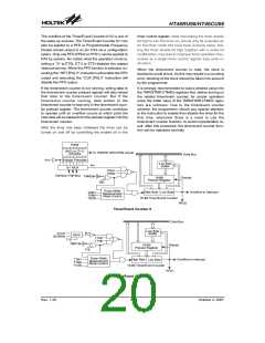
Timer/Event Counter 2
P
P
F
F
D
D
0
1
M
U
T
Q
P
F
D
X
P
A
3
D
a
t
a
C
T
R
L
P
F
D
S
o
u
r
c
e
(
O
p
t
i
o
n
)
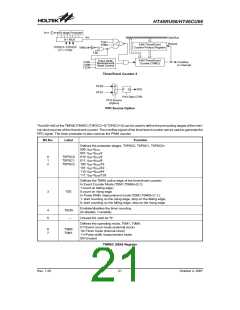
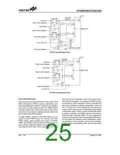
PFD Source Option
The bit0~bit2 of the TMR0C/TMR2C (T0PSC2~0/ T2PSC2~0) can be used to define the pre-scaling stages of the inter-
nal clock sources of the timer/event counter. The overflow signal of the timer/event counter can be used to generate the
PFD signal. The timer prescaler is also used as the PWM counter.
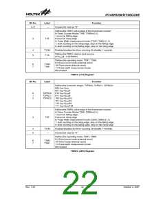
Bit No.
Label
Function
Defines the prescaler stages, T0PSC2, T0PSC1, T0PSC0=
000: fINT=fSYS
001: fINT=fSYS/2
010: fINT=fSYS/4
011: fINT=fSYS/8
100: fINT=fSYS/16
101: fINT=fSYS/32
110: fINT=fSYS/64
111: fINT=fSYS/128
0
1
2
T0PSC0
T0PSC1
T0PSC2
Defines the TMR0 active edge of the timer/event counter:
In Event Counter Mode (T0M1,T0M0)=(0,1):
1:count on falling edge;
3
T0E
0:count on rising edge
In Pulse Width measurement mode (T0M1,T0M0)=(1,1):
1: start counting on the rising edge, stop on the falling edge;
0: start counting on the falling edge, stop on the rising edge
Enables/disables the timer counting
(0=disable; 1=enable)
4
5
T0ON
¾
Unused bit, read as ²0²
Defines the operating mode, T0M1, T0M0:
01=Event count mode (external clock)
10=Timer mode (internal clock)
11=Pulse width measurement mode
00=Unused
6
7
T0M0
T0M1
TMR0C (0EH) Register
Rev. 1.20
21
October 2, 2007

 HOLTEK [ HOLTEK SEMICONDUCTOR INC ]