HT46RU66/HT46CU66
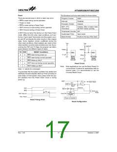
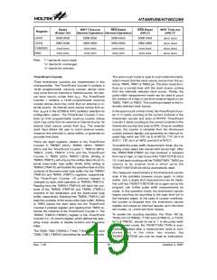
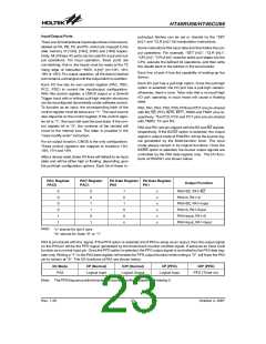
Reset
WDT Time-out
RES Reset
RES Reset
(HALT)
WDT Time-out
(HALT)*
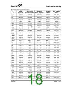
Register
(Power On)
(Normal Operation) (Normal Operation)
UCR1
0000 00x0
0000 0000
xxxx xxxx
xxxx xxxx
0000 00x0
0000 0000
xxxx xxxx
xxxx xxxx
0000 00x0
0000 0000
xxxx xxxx
xxxx xxxx
0000 00x0
0000 0000
xxxx xxxx
xxxx xxxx
uuuu uuuu
uuuu uuuu
uuuu uuuu
uuuu uuuu
UCR2
TXR/RXR
BRG
Note:
²*² stands for warm reset
²u² stands for unchanged
²x² stands for unknown
Timer/Event Counter
The event count mode is used to count external events,
which means that the clock source comes from the ex-
ternal, TMR0, TMR1 or TMR2 pin. The timer mode func-
tions as a normal timer with the clock source coming
from the internally selected clock source. Finally, the
pulse width measurement mode can be used to count
the duration of a high or low level external signal on pin
TMR0, TMR1 or TMR2. The counting is based on the in-
ternally selected clock source.
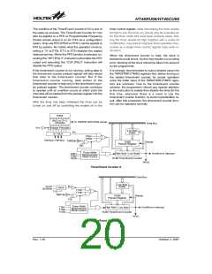
Three timer/event counters are implemented in this
microcontroller. The Timer/Event Counter 0 contains a
16-bit programmable count-up counter whose clock
may come from an external or internal source. Its inter-
nal clock source comes from fSYS. The Timer/Event
Counter 1 contains a 16-bit programmable count-up
counter whose clock may come from an external or in-
ternal source. Its internal clock source comes from ei-
ther fSYS/4 or the 32768Hz RTC oscillator selected via
configuration option. The Timer/Event Counter 2 con-
tains an 8-bit programmable count-up counter whose
clock may come from an external or internal source. Its
internal clock source comes from fSYS. The external
clock input allows the user to count external events,
measure time intervals or pulse widths, or generate an
accurate time base.
In the event count or timer mode, the Timer/Event Coun-
ter 0 (1) starts counting at the current contents in the
timer/event counter and ends at FFFFH. Timer/Event
Counter 2 starts counting at the current contents in the
timer/event counter and ends at FFH. Once an overflow
occurs, the counter is reloaded from the timer/event
counter preload register, and generates an interrupt re-
quest flag which are T0F; bit 6 of INTC0, T1F; bit 4 of
INTC1, T2F; bit 4 of MFIC and bit 6 of INTC1.
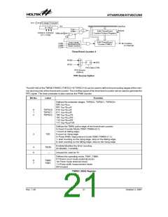
There are eight registers related to the Timer/Event
Counter 0; TMR0H (0CH), TMR0L (0DH), TMR0C
(0EH) and the Timer/Event Counter 1; TMR1H (0FH),
TMR1L (10H), TMR1C (11H) and the Timer/Event
Counter 2; TMR2 (2CH) TMR2C (2DH). Writing to
TMR0L (TMR1L) will only put the written data into an in-
ternal lower-order byte buffer (8-bit) while writing to
TMR0H (TMR1H) will transfer the specified data and the
contents of the lower-order byte buffer into the TMR0H
(TMR1H) and TMR0L (TMR1L) registers, respectively.
The Timer/Event Counter 1/0 preload register is
changed by each write operation to TMR0H (TMR1H).
Reading from the TMR0H (TMR1H) will latch the con-
tents of the TMR0H (TMR1H) and TMR0L (TMR1L)
counters to the destination and the lower-order byte
buffer, respectively. Reading from TMR0L (TMR1L) will
read the contents of the lower-order byte buffer. Writing
to TMR2 places the start value into the Timer/Event
Counter 2 preload register, and reading from TMR2 re-
trieves the contents of the Timer/Event Counter 2. The
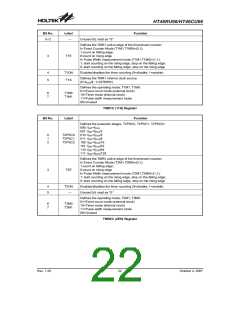
TMR0C (TMR1C,TMR2C) register is the Timer/Event
Counter 0 (1, 2) control register, which defines the oper-
ating mode, enable or disable function and the active
edge.
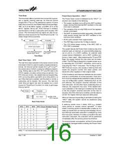
To enable the pulse width measurement mode, the op-
erating mode select bits should both be set high. After
the TMR0/TMR1/TMR2 pin has received a transient
from low to high, or high to low if the T0E/T1E/T2E bit is
²0², it will start counting until the TMR0/TMR1/ TMR2 pin
returns to its original level a which point the
T0ON/T1ON/T2ON bit will be auomatically reset.
The measured result remains in the timer/event counter
even if the activated transient occurs again. In other
words, only a single shot measurement can be made.
Not until the T0ON/T1ON/T2ON bit is again set by the
program, can further pulse width measurements be
made. In this operation mode, the timer/event counter
begins counting not according to the logic level but to
the transient edges. In the case of counter overflows,
the counter is reloaded from the timer/event counter
register and issues an interrupt request, as in the other
two modes, i.e., event and timer modes.
To enable the counting operation, the Timer ON bit,
T0ON; bit 4 of TMR0C, T1ON; bit 4 of TMR1C, or T2ON;
bit 4 of TMR2C, should be set to 1. In the pulse width
measurement mode, the T0ON/T1ON/ T2ON is auto-
matically cleared after a measurement cycle is com-
pleted. But in the other two modes, the
T0ON/T1ON/T2ON can only be reset by instructions.
The T0M0, T0M1 (TMR0C), T1M0, T1M1 (TMR1C) and
T2M0, T2M1 (TMR2C) bits define the operational mode.
Rev. 1.20
19
October 2, 2007

 HOLTEK [ HOLTEK SEMICONDUCTOR INC ]