HT46RU66/HT46CU66
Time Base
Power Down Operation - HALT
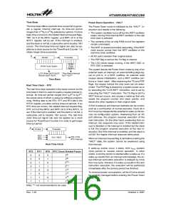
The time base offers a periodic time-out period to gener-
ate a regular internal interrupt. Its time-out period
ranges from 212/fS to 215/fS selected by options. If a time
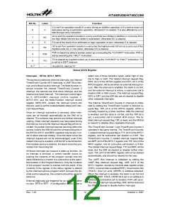
base time-out occurs, the related interrupt request flags,
TBF; bit 5 of the MFIC register, and MFF; bit 6 of the
INTC1 register, will be set. If the interrupt is enabled,
and the stack is not full, a subroutine call to location 18H
occurs. The time base time-out signal can also be ap-
plied as a clock source for the Timer/Event Counter 1 to
obtain longer time-out periods.
The Power Down mode is initialised by the ²HALT² in-
struction and results in the following.
·
The system oscillator turns off but the WDT oscillator
keeps running if the internal WDT oscillator or the real
time clock is selected.
·
The contents of the on-chip RAM and of the registers
remain unchanged.
·
The WDT is cleared and starts recounting, if the WDT
clock source comes from the WDT oscillator or the
real time clock oscillator.
f
s
·
All I/O ports maintain their original status.
D
i
v
i
d
e
r
P
r
e
s
c
a
l
e
r
·
The PDF flag is set but the TO flag is cleared.
·
The LCD driver keeps running, if the WDT OSC or
R
O
M
RTC OSC is selected.
R
O
M
C
o
d
e
O
p
t
i
o
n
C
o
d
e
O
p
t
i
o
n
The system leaves the Power Down mode by way of an
external reset, an interrupt, an external falling edge sig-
nal on port A, or a WDT overflow. An external reset
causes device initialisation, and a WDT overflow per-
forms a ²warm reset². After examining the TO and PDF
flags, the reason behind the chip reset can be deter-
mined. The PDF flag is cleared by a system power-up or
by executing the ²CLR WDT² instruction, and is set by
executing the ²HALT² instruction. The TO flag is set if a
WDT time-out occurs, and causes a wake-up that only
resets the program counter and stack pointer, and
leaves the other registers in their original state.
2
8
L
C
D
D
r
i
v
e
r
(
f
S
/
2
~
f
S
/
2
)
T
i
m
e
B
a
s
e
I
n
t
e
r
r
u
p
t
2
9
1
2
1
5
B
u
z
z
e
r
(
f
S
/
2
~
f
S
/
2
)
f
S
/
2
S
~ f / 2
Time Base
Real Time Clock - RTC
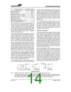
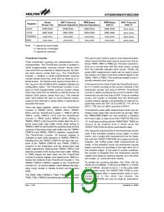
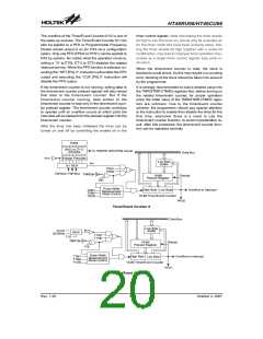
The real time clock operates in the same manner as the
time base in that it is used to supply a regular internal in-
terrupt. Its time-out period ranges from fS/28 to fS/215
,
the actual value of which is setup by software program-
ming. Writing data to the RT2, RT1 and RT0 bits in the
RTCC register, provides various time-out periods. If an
RTC time-out occurs, the related interrupt request flag,
RTF; bit 6 of the MFIC and MFF; bit 6 of the INTC1, is
set. If the interrupt is enabled, and the stack is not full, a
subroutine call to location 18H occurs. The real time
clock time-out signal can also be applied as a clock
source for Timer/Event Counter 0 in order to get longer
time-out period.
A Port A wake-up and interrupt methods can be consid-
ered as a continuation of normal execution. Each bit in
Port A can be independently selected to wake up the de-
vice via configuration options. Awakening from an I/O
port stimulus, the program resumes execution of the
next instruction. On the other hand, awakening from an
interrupt, two sequence may occur. If the related inter-
rupt is disabled or the interrupt is enabled but the stack
is full, the program resumes execution at the next in-
struction. But if the interrupt is enabled, and the stack is
not full, the regular interrupt response takes place.
f
S
D
i
v
i
d
e
r
P
r
e
s
c
a
l
e
r
R
R
T
T
2
1
8
1
5
2
/
f
S
~
2
/
f
8
t
o
1
M
U
X
When an interrupt request flag is set before entering the
²HALT² state, the system cannot be awakened using
that interrupt.
R
T
0
R
T
C
I
n
t
e
r
r
u
p
t
Real Time Clock
If wake-up events occur, it takes 1024 tSYS (system
clock period) to resume normal operation. In other
words, a dummy period is inserted after a wake-up. If a
wake-up results from an interrupt acknowledge, the ac-
tual interrupt subroutine execution is delayed by more
than one cycle. However, if a wake-up results in the next
instruction execution, the execution will be performed
immediately after the dummy period has finished.
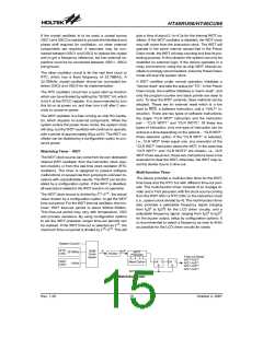
RT2
0
RT1
0
RT0 RTC Clock Divided Factor
0
1
0
1
0
1
0
1
28*
29*
0
0
0
1
210
211
*
0
1
*
1
0
212
213
214
215
To minimize power consumption, all the I/O pins should
be carefully managed before entering the Power Down
state.
1
0
1
1
1
1
Note: ²*² not recommended to be used
Rev. 1.20
16
October 2, 2007

 HOLTEK [ HOLTEK SEMICONDUCTOR INC ]