HT46RU66/HT46CU66
If the crystal oscillator is to be used, a crystal across
OSC1 and OSC2 is needed to provide the feedback and
phase shift required for oscillation, no other external
components are required. A resonator may be con-
nected between OSC1 and OSC2 to replace the crystal
and to get a frequency reference, but two external ca-
pacitors must be be connected between OSC1, OSC2
and ground.
give a time of about 2.1s~4.3s for the internal WDT os-
cillator. If the WDT oscillator is disabled, the WDT clock
may still come from the instruction clock. The WDT will
operate in the same manner except that in the Power
Down mode, the WDT will stop counting and lose its pro-
tecting purpose. In this situation the system can only be
restarted by external logic. If the device operates in a
noisy environment, using the on-chip WDT internal os-
cillator is strongly recommended, since the Power Down
mode will stop the system clock.
The other oscillator circuit is for the real time clock or
RTC, which has a fixed frequency of 32.768kHz. A
32.768kHz crystal oscillator should be connected be-
tween OSC3 and OSC4 for its implementation.
A WDT overflow under normal operation initialises a
²device reset² and sets the status bit ²TO². In the Power
Down mode, the overflow initialises a ²warm reset², and
only the program counter and stack pointer are reset to
zero. To clear the WDT contents, three methods can be
adopted. These are an external reset which is a low
level to RES, a software instruction, and a ²HALT² in-
struction. There are two types of software instructions;
the single ²CLR WDT² instruction and the instruction
pair - ²CLR WDT1² and ²CLR WDT2². Of these two
types of instruction, only one type of instruction can be
active at a time depending on the options - ²CLR WDT²
times selection option. If the ²CLR WDT² is selected,
i.e., CLR WDT times equal one, any execution of the
²CLR WDT² instruction clears the WDT. In the case that
²CLR WDT1² and ²CLR WDT2² are chosen, i.e., CLR
WDT times equal two, these two instructions have to be
executed to clear the WDT, otherwise, the WDT may re-
set the device due to a time-out.
The RTC oscillator circuit has a quick start up function
which can be activated by setting the ²QOSC² bit, which
is bit 4 of the RTCC register. It is recommended to turn
this bit on at power on, and then turn it off after 2 sec-
onds to conserve power.
The WDT oscillator is a free running on-chip RC oscilla-
tor, which requires no external components. When the
system enters the power down mode, the system clock
will stop, but the WDT oscillator will continue to operate,
with a period of approximately 65ms at 5V. The WDT os-
cillator can be disabled by a configuration option to con-
serve power.
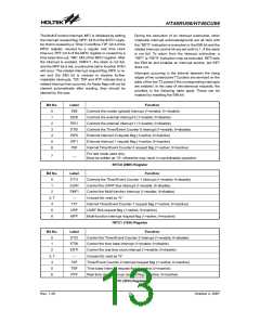
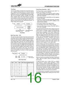
Watchdog Timer - WDT
The WDT clock source can come from its own dedicated
internal WDT oscillator, from the instruction clock (sys-
tem clock/4), or from the real time clock oscillator (RTC
oscillator). The timer is designed to prevent software
malfunctions or sequences from jumping to unknown lo-
cations with unpredictable results. The WDT can be dis-
abled by a configuration option. If the WDT is disabled,
all executions related to the WDT result in no operation.
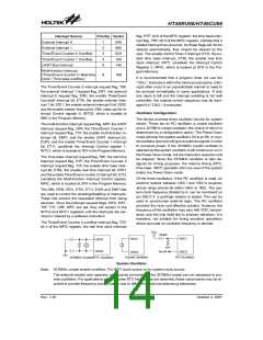
Multi-function Timer
The device provides a multi-function timer for the WDT,
time base and the RTC but with different time-out peri-
ods. The multi-function timer consists of an 8-stage di-
vider and a 7-bit prescaler, with the clock source coming
from the WDT OSC or RTC OSC or the instruction clock
(i.e., system clock divided by 4). The multi-function timer
also provides a selectable frequency signal (ranging
from fS/22 to fS/28) for the LCD driver circuits, and a
selectable frequency signal, ranging from fS/22 to fS/29,
for the buzzer output, setup by configuration options. It
is recommended to select a frequency as near to 4kHz
as possible for the LCD driver circuits for clarity.
The WDT clock source is divided by 212~215 , the actual
value chosen by a configuration option, to get the WDT
time-out period. For the WDT internal oscillator, the min-
imum WDT time-out period is about 300ms~600ms.
This time-out period may vary with temperature, VDD
and process variations. By using configuration options
to set the WDT prescaler, longer time-out periods can
be realised. If the WDT time-out is selected as 215, the
maximum time-out period is divided by 215~216. This will
S
y
s
t
e
m
C
l
o
c
k
/
4
8
R
T
C
f
S
R
O
M
S
f / 2
3
2
7
6
8
H
z
W
D
T
D
i
v
i
d
e
r
O
W
S
C
C
o
d
e
P
r
e
s
c
a
l
e
r
T
f
f
f
f
i
m
e
-
o
u
t
R
e
s
e
t
O
p
t
i
o
n
1
1
1
1
5
4
3
2
1
1
1
1
6
5
4
3
S
S
S
S
/
/
/
/
2
2
2
2
~
~
~
~
f
f
f
f
S
S
S
S
/
/
/
/
2
2
2
2
D
T
M
a
s
k
O
p
t
i
o
n
C
K
T
C
K
T
1
2
k
H
z
O
S
C
R
R
W
D
T
C
l
e
a
r
Watchdog Timer
Rev. 1.20
15
October 2, 2007

 HOLTEK [ HOLTEK SEMICONDUCTOR INC ]