HT46R12
f
S
Y
S
8
-
s
t
a
g
e
P
r
e
s
c
a
l
e
r
f
I N T
8
-
1
M
U
X
D
a
t
a
b
u
s
T
0
P
S
C
2
~
T
0
P
S
C
0
(
1
/
1
~
1
/
1
2
8
)
T
0
M
1
R
e
l
o
a
d
8
-
b
i
t
T
i
m
e
r
/
E
v
e
n
t
C
o
u
n
t
e
r
T
0
M
0
T
M
R
0
P
r
e
l
o
a
d
R
e
g
i
s
t
e
r
T
0
E
8
-
b
i
t
T
i
m
e
r
/
E
v
e
n
t
P
u
l
s
e
W
i
n
d
t
h
O
v
e
r
f
l
o
w
T
0
M
1
M
e
a
s
u
r
e
m
e
n
t
C
o
u
n
t
e
r
(
T
M
R
0
)
T
o
I
n
t
e
r
r
u
p
t
T
0
M
0
M
o
d
e
C
o
t
r
o
l
T
0
O
N
P
F
D
0
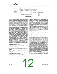
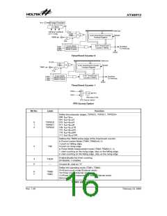
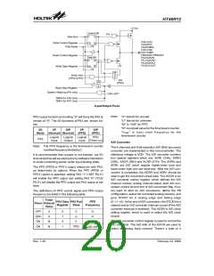
Timer/Event Counter 0
D
a
t
a
b
u
s
S
Y
S
T
1
M
1
R
e
l
o
a
d
8
-
b
i
t
T
i
m
e
r
/
E
v
e
n
t
C
o
u
n
t
e
r
T
1
M
0
T
M
R
1
P
r
e
l
o
a
d
R
e
g
i
s
t
e
r
T
1
E
8
-
b
i
t
T
i
m
e
r
/
E
v
e
n
t
P
u
l
s
e
W
i
d
t
h
O
v
e
r
f
l
o
w
T
1
M
1
M
e
a
s
u
r
e
m
e
n
t
C
o
u
n
t
e
r
(
T
M
R
1
)
T
o
I
n
t
e
r
r
u
p
t
T
1
M
0
M
o
d
e
C
o
n
t
r
o
l
T
1
O
N
P
F
D
1
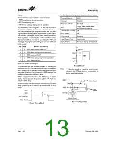
Timer/Event Counter 1
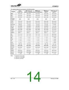
P
P
F
F
D
D
0
1
M
U
T
Q
P
F
D
X
P
A
3
D
a
t
a
C
T
R
L
P
F
D
S
o
u
r
c
e
O
p
t
i
o
n
PFD Source Option
Bit No.
Label
Function
Define the prescaler stages, T0PSC2, T0PSC1, T0PSC0=
000: fINT=fSYS
001: fINT=fSYS/2
0
1
2
T0PSC0
T0PSC1
T0PSC2
010: fINT=fSYS/4
011: fINT=fSYS/8
100: fINT=fSYS/16
101: fINT=fSYS/32
110: fINT=fSYS/64
111: fINT=fSYS/128
Defines the TMR0 active edge of the timer/event counter:
In Event Counter Mode (T0M1,T0M0)=(0,1):
1:count on falling edge;
3
T0E
0:count on rising edge
In Pulse Width measurement mode (T0M1,T0M0)=(1,1):
1: start counting on the rising edge, stop on the falling edge;
0: start counting on the falling edge, stop on the rising edge
Enable/disable the timer counting
(0=disable; 1=enable)
4
5
T0ON
¾
Unused bit, read as ²0²
Define the operating mode (T0M1, T0M0)
01=Event count mode (External clock)
10=Timer mode (Internal clock)
6
7
T0M0
T0M1
11=Pulse Width measurement mode (External clock)
00=Unused
TMR0C (0EH) Register
Rev. 1.20
16
February 24, 2006
图片预览")
 HOLTEK [ HOLTEK SEMICONDUCTOR INC ]