HT46R12
S
y
s
t
e
m
C
l
o
c
k
/
4
8
s
f / 2
M
a
s
k
f
s
W
D
T
P
r
e
s
c
a
l
e
r
D
i
v
i
d
e
r
o
p
t
i
o
n
s
e
l
e
c
t
W
D
T
O
S
C
T
i
m
e
-
o
u
t
R
e
s
e
t
M
a
s
k
O
p
t
i
o
n
1
1
1
1
6
5
4
3
f
f
f
f
s
s
s
s
/
/
/
/
2
2
2
2
W
D
T
C
l
e
a
r
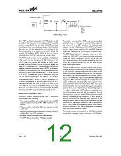
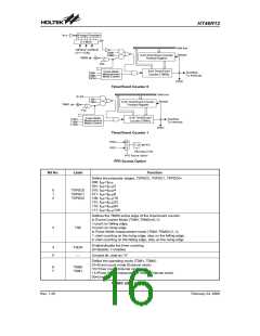
Watchdog Timer
If the WDT oscillator is disabled, the WDT clock may still
come from the instruction clock and operate in the same
manner except that in the halt state the WDT may stop
counting and lose its protecting purpose. In this situation
the logic can only be restarted by external logic. If the
device operates in a noisy environment, using the
on-chip RC oscillator (WDT OSC) is strongly recom-
mended, since the HALT will stop the system clock.
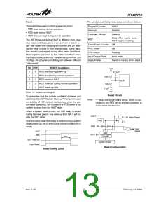
The system can leave the HALT mode by means of an
external reset, an interrupt, an external falling edge sig-
nal on port A or a WDT overflow. An external reset
causes a device initialization and the WDT overflow per-
forms a ²warm reset². After the TO and PDF flags are
examined, the reason for chip reset can be determined.
The PDF flag is cleared by a system power-up or exe-
cuting the ²CLR WDT² instruction and is set when exe-
cuting the ²HALT² instruction. The TO flag is set if the
WDT time-out occurs, and causes a wake-up that only
resets the program counter and SP, the other circuits
keep their original status.
The WDT overflow under normal operation will initialize a
²chip reset² and set the status bit TO. Whereas in the
HALT mode, the overflow will initialize a ²warm reset²
wherein only the program counter and stack pointer are
reset to 0. To clear the WDT contents, three methods are
adopted; external reset (a low level to RES), software in-
structions, or a HALT instruction. The software instructions
include CLR WDT and the other set - CLR WDT1 and
CLR WDT2. Of these two types of instruction, only one
can be active depending on the options - ²CLR WDT
times selection option². If the ²CLR WDT² is selected (i.e.
CLRWDT times equal 1), any execution of the CLR WDT
instruction will clear the WDT. In case ²CLR WDT1² and
²CLR WDT2² are chosen (i.e. CLRWDT times equal two),
these two instructions must be executed to clear the WDT,
otherwise, the WDT may reset the chip due to time-out.
The port A wake-up and interrupt methods can be con-
sidered as a continuation of normal execution. Each bit
in port A can be independently selected to wake up the
device by options. Awakening from an I/O port stimulus,
the program will resume execution of the next instruc-
tion. If it is awakening from an interrupt, two sequences
may occur. If the related interrupt is disabled or the inter-
rupt is enabled but the stack is full, the program will re-
sume execution at the next instruction. If the interrupt is
enabled and the stack is not full, the regular interrupt re-
sponse takes place. If an interrupt request flag is set to
²1² before entering the HALT mode, the wake-up func-
tion of the related interrupt will be disabled. Once a
wake-up event occurs, it takes 1024 tSYS (system clock
period) to resume normal operation. In other words, a
dummy period will be inserted after wake-up. If the
wake-up results from an interrupt acknowledge, the ac-
tual interrupt subroutine execution will be delayed by
one or more cycles. If the wake-up results in the next in-
struction execution, this will be executed immediately
after the dummy period is finished.
Power Down Operation - HALT
The HALT mode is initialized by the ²HALT² instruction
and results in the following:
·
The system oscillator will be turned off but the WDT
oscillator keeps running (if the WDT oscillator is se-
lected).
·
·
The contents of the on chip RAM and registers remain
unchanged.
To minimize power consumption, all the I/O pins should
be carefully managed before entering the HALT status.
WDT will be cleared and recounted again (if the WDT
clock is from the WDT oscillator).
·
·
All of the I/O ports maintain their original status.
The PDF flag is set and the TO flag is cleared.
Rev. 1.20
12
February 24, 2006
图片预览")
 HOLTEK [ HOLTEK SEMICONDUCTOR INC ]