HT46R12
Timer/Event Counter
The measured result remains in the timer/event counter
even if the activated transient occurs again. In other
words, only 1-cycle measurement can be made until the
T0ON/T1ON is set. The cycle measurement will
re-function as long as it receives further transient pulse.
In this operation mode, the timer/event counter begins
counting not according to the logic level but to the tran-
sient edges. In the case of counter overflows, the coun-
ter is reloaded from the timer/event counter register and
issues an interrupt request, as in the other two modes,
i.e., event and timer modes.
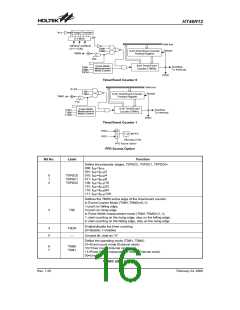
Two timer/event counters (TMR0,TMR1) are imple-
mented in the microcontroller. The Timer/Event Counter
0 contains an 8-bit programmable count-up counter and
the clock may come from an external source or an inter-
nal clock source. An internal clock source comes from
f
SYS. The Timer/Event Counter 1 contains an 8-bit pro-
grammable count-up counter and the clock may come
from an external source or an internal clock source. An
internal clock source comes from fSYS/4. The external
clock input allows the user to count external events,
measure time intervals or pulse widths, or to generate
an accurate time base.
To enable the counting operation, the Timer ON bit
(T0ON; bit 4 of the TMR0C or T1ON; bit 4 of the
TMR1C) should be set to 1. In the pulse width measure-
ment mode, the T0ON/T1ON is automatically cleared
after the measurement cycle is completed. But in the
other two modes, the T0ON/T1ON can only be reset by
instructions. The overflow of the Timer/Event Counter
0/1 is one of the wake-up sources and the Timer/Event
Counter 0/1 can also be applied to a PFD (Programma-
ble Frequency Divider) output at PA3 by options. Only
one PFD (PFD0 or PFD1) can be applied to PA3 by op-
tions. No matter what the operation mode is, writing a 0
to ET0I or ET1I disables the related interrupt service.
When the PFD function is selected, executing ²SET
[PA].3² instruction will enable the PFD output and exe-
cuting ²CLR [PA].3² instruction will disable the PFD out-
put.
Using the internal system clock, the timer/event counter
is only one reference time base. The internal clock
source comes from external events, measure time inter-
vals or pulse widths, or generate an accurate time base.
Using the internal clock allows the user to generate an
accurate time base.
There are four registers related to the Timer/Event
Counter 0; TMR0 (0DH), TMR0C (0EH), the
Timer/Event Counter 1; TMR1(10H), TMR1C (11H).
Writing TMR0/TMR1 makes the starting value be placed
in the Timer/Event Counter 0/1 preload register and
reading TMR0/TMR1 retrieves the contents of the
Timer/Event Counter 0/1. The TMR0C and TMR1C are
Timer/Event Counter control register 0/1, which defines
the operating mode, counting enable or disable and an
active edge.
In the case of timer/event counter OFF condition, writing
data to the timer/event counter preload register also re-
loads that data to the timer/event counter. But if the
timer/event counter is turn on, data written to the
timer/event counter is kept only in the timer/event coun-
ter preload register. The timer/event counter still contin-
ues its operation until an overflow occurs.
The T0M0/T1M0 and T0M1/T1M1 bits define the opera-
tion mode. The event count mode is used to count exter-
nal events, which means that the clock source is from an
external (TMR0, TMR1) pin. The timer mode functions
as a normal timer with the clock source coming from the
internal selected clock source. The pulse width mea-
surement mode can be used to count the high or low
level duration of the external signal (TMR0, TMR1), and
the counting is based on the internal selected clock
source.
When the timer/event counter (reading TMR0/TMR1) is
read, the clock is blocked to avoid errors, as this may re-
sults in a counting error. Blocking of the clock should be
taken into account by the programmer.
In the event count or timer mode, the timer/event coun-
ter 0/1 starts counting at the current contents in the
timer/event counter and ends at FFH. Once an overflow
occurs, the counter is reloaded from the timer/event
counter preload register, and generates an interrupt re-
quest flag (T0F; bit 6 of the INTC0, T1F; bit 4 of the
INTC1).
It is strongly recommended to load a desired value into
the TMR0/TMR1 register first, before turning on the re-
lated timer/event counter, for proper operation since the
initial value of TMR0/TMR1 is unknown. Due to the
timer/event scheme, the programmer should pay spe-
cial attention on the instruction to enable then disable
the timer for the first time, whenever there is a need to
use the timer/event function, to avoid unpredictable re-
sult. After this procedure, the timer/event function can
be operated normally.
In the pulse width measurement mode with the values of
the T0ON/T1ON and T0E/T1E bits equal to ²1², after the
TMR0 (TMR1) has received a transient from low to high
(or high to low if the T0E/T1E bit is ²0²), it will start count-
ing until the TMR0 (TMR1) returns to the original level
and resets the T0ON/T1ON.
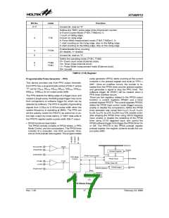
The bit0~bit2 of the TMR0C can be used to define the
pre-scaling stages of the internal clock sources of
timer/event counter. The definitions are as shown. The
overflow signal of the timer/event counter can be used
to generate the PFD signal.
Rev. 1.20
15
February 24, 2006
图片预览")
 HOLTEK [ HOLTEK SEMICONDUCTOR INC ]