HT46R12
V
D
D
During the execution of an interrupt subroutine, other in-
terrupt acknowledge are held until the ²RETI² instruction
is executed or the EMI bit and the related interrupt control
bit are set to 1 (if the stack is not full). To return from the
interrupt subroutine, ²RET² or ²RETI² may be invoked.
RETI will set the EMI bit to enable an interrupt service,
but RET will not.
O
S
C
1
O
S
C
1
S
Y
S
O
S
C
2
O
S
C
2
N
M
O
S
O
p
e
n
D
r
a
i
n
C
r
y
s
t
a
l
O
s
c
i
l
l
a
t
o
r
R
C
O
s
c
i
l
l
a
t
o
r
System Oscillator
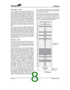
Interrupts, occurring in the interval between the rising
edges of two consecutive T2 pulses, will be serviced on
the latter of the two T2 pulses, if the corresponding inter-
rupts are enabled. In the case of simultaneous requests
the following table shows the priority that is applied.
These can be masked by resetting the EMI bit.
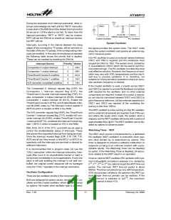
the signal provides the system clock. The HALT mode
stops the system oscillator and ignores an external sig-
nal to conserve power.
If an RC oscillator is used, an external resistor between
OSC1 and VSS is required and the resistance must
range from 24kW to 1MW. The system clock, divided by
4, is available on OSC2, which can be used to synchro-
nize external logic. The RC oscillator provides the most
cost effective solution. However, the frequency of oscil-
lation may vary with VDD, temperatures and the chip it-
self due to process variations. It is, therefore, not
suitable for timing sensitive operations where an accu-
rate oscillator frequency is desired.
Interrupt Source
Priority Vector
Comparator 0 output interrupt
Comparator 1 output interrupt
Timer/Event Counter 0 overflow
Timer/Event Counter 1 overflow
A/D converter completed overflow
1
2
3
4
5
04H
08H
0CH
10H
14H
If the Crystal oscillator is used, a crystal across OSC1
and OSC2 is needed to provide the feedback and phase
shift required for the oscillator, and no other external
components are required. Instead of a crystal, a resona-
tor can also be connected between OSC1 and OSC2 to
get a frequency reference, but two external capacitors in
OSC1 and OSC2 are required (if the oscillating fre-
quency is less than 1MHz).
The Comparator 0 interrupt request flag (C0F), the
Comparator 1 interrupt request flag (C1F), the
Timer/Event 0 Counter interrupt request flag (T0F), En-
able Comparator 0 output interrupt bit (EC0I), Enable
Comparator 1 output interrupt bit (EC1I), Enable the
Timer/Event Counter 0 (ET0I), and Enable Master Inter-
rupt bit (EMI) make up The Interrupt Control register 0
(INTC0) which is located at 0BH in the RAM.
The WDT oscillator is a free running on-chip RC oscillator,
and no external components are required. Even if the sys-
tem enters the power down mode, the system clock is
stopped, but the WDT oscillator still works with a period of
approximately 65ms @ 5V. The WDT oscillator can be dis-
abled by options to conserve power.
The A/D converter request flag (ADF), the Timer/Event
Counter 1 interrupt request flag (T1F), enable A/D con-
verter interrupt bit (EADI), enable Timer/Event Counter
1 interrupt bit (ET1I), constitute the Interrupt Control reg-
ister 1 (INTC1) which is located at 1EH in the RAM.
EMI, EC0I, EC1I, ET0I, ET1I, and EADI are all used to
control the enable/disable status of interrupts. These
bits prevent the requested interrupt from being serviced.
Once the interrupt request flags (C0F, C1F, T0F, T1F,
ADF) are all set, they remain in the INTC1 or INTC0 re-
spectively until the interrupts are serviced or cleared by
software instruction.
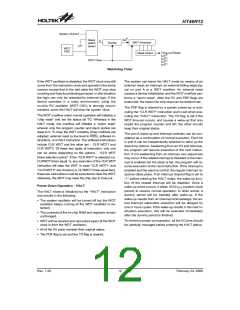
Watchdog Timer - WDT
The WDT clock source is implemented by a dedicated
RC oscillator (WDT oscillator) or instruction clock (sys-
tem clock divided by 4) determined by options. This
timer is designed to prevent a software malfunction or
sequence jumping to an unknown location with unpre-
dictable results. The Watchdog Timer can be disabled
by option. If the Watchdog Timer is disabled, all execu-
tions related to the WDT result in no operation.
It is recommended that a program does not use the
²CALL subroutine² within the interrupt subroutine. Inter-
rupts often occur in an unpredictable manner or need to
be serviced immediately in some applications. If only one
stack is left and enabling the interrupt is not well con-
trolled, the original control sequence will be damaged
once the ²CALL² operates in the interrupt subroutine.
Once an internal WDT oscillator (RC oscillator with a pe-
riod of 65ms/@5V normally) is selected, it is divided by
213, 214 , 215 or 216 (by options) to get the WDT time-out
period. The minimum WDT time-out period is about
600ms. This time-out period may vary with temperature,
VDD and process variations. By selection the WDT op-
tions, longer time-out periods can be realized. If the
WDT time-out is selected to fS/216, the maximum
time-out period is about 4.7s.
Oscillator Configuration
There are two oscillator circuits in the microcontroller.
Both are designed for system clocks, namely the RC os-
cillator and the Crystal oscillator, which are determined
by options. No matter what oscillator type is selected,
Rev. 1.20
11
February 24, 2006
图片预览")
 HOLTEK [ HOLTEK SEMICONDUCTOR INC ]